A high-efficiency derusting device for iron products used in hardware production and its use method

A technology for iron products and hardware, which is applied in the field of high-efficiency derusting devices for iron products used in hardware production. It can solve the problems of high labor intensity and manual handling, and achieve the effects of reducing labor intensity, high work efficiency, and ensuring derusting effect

Active Publication Date: 2021-07-27
安徽省阜南志峰工艺品有限公司
View PDF1 Cites 0 Cited by
  • Summary
  • Abstract
  • Description
  • Claims
  • Application Information

AI Technical Summary

Problems solved by technology

[0003] The purpose of the present invention is to provide a high-efficiency derusting device for iron products used in hardware manufacturing and its use method. The invention supports the iron product plates by setting a moving bracket above the supporting base plate, and drives the iron products through a displacement motor in cooperation with pulleys and belts. Move the bracket to carry the iron product plate, so that the iron product plate passes under the derusting roller for derusting, which solves the technical problem of manual handling of the iron product plate and high labor intensity when the iron product derusting is used in traditional hardware manufacturing;

Method used


Image

  • A high-efficiency derusting device for iron products used in hardware production and its use method
  • A high-efficiency derusting device for iron products used in hardware production and its use method
  • A high-efficiency derusting device for iron products used in hardware production and its use method

Examples


Embodiment Construction

[0035] The technical solutions of the present invention will be clearly and completely described below in conjunction with the embodiments. Apparently, the described embodiments are only some of the embodiments of the present invention, not all of them. Based on the embodiments of the present invention, all other embodiments obtained by persons of ordinary skill in the art without creative efforts fall within the protection scope of the present invention.

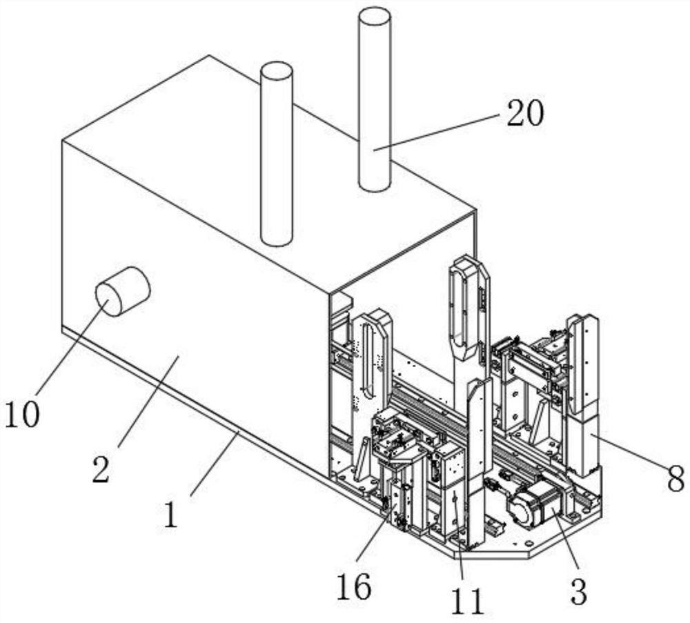
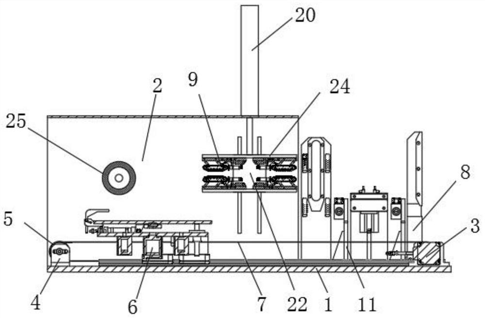
[0036] Such as Figure 1-7 As shown, a high-efficiency derusting device for iron products for hardware production includes a support base plate 1, and a housing 2 is fixedly installed on the upper surface of the support base plate 1 by welding, and openings are provided at both ends of the housing 2. A displacement motor 3 is fixedly installed on one end of the upper surface of the support base plate 1, a pulley 5 is fixedly installed on the output shaft end of the displacement motor 3, and a pulley mounting seat 4 is fixed...


PUM


Abstract

The invention discloses a high-efficiency derusting device for iron products used in hardware manufacturing and a method for using the derusting device. The derusting device includes a support base plate. A shell is fixedly installed on the upper surface of the support base plate through welding, and the support base plate moves along the horizontal direction. A mobile bracket is installed, the output shaft end of the derusting motor is connected with the derusting roller, and the upper surface of the support base plate is fixedly equipped with a lifting cylinder one, and the top of the output rod of the lifting cylinder one is fixedly equipped with a centering cylinder. The end of the output rod of the middle cylinder is fixedly installed with a centering plate, one end of the connecting rod is fixedly connected with one end of the slide bar, and one end of the slide bar is fixedly connected with a supporting short plate, and two Clamp assembly; the derusting device does not need to manually carry the iron product plate, which greatly reduces the labor intensity. It can turn over the iron product plate to remove rust. The work efficiency is high and the design is reasonable, which ensures the derusting effect.

Description

technical field [0001] The invention relates to a derusting device, in particular to a high-efficiency derusting device for iron products used in hardware manufacturing and a use method thereof. Background technique [0002] Hardware needs to carry out derusting treatment to iron products before processing, so derusting device plays an important role in hardware processing, but existing derusting device still has deficiencies; Patent document (CN207480334U) discloses a kind of High-efficiency derusting device for iron products. The derusting device needs to manually carry the plate during the derusting process, which is labor-intensive and cannot automatically turn over the plate. It needs to derust one side first, and then take it out by turning it over manually. Rust removal on the other side is cumbersome, time-consuming and laborious, and the work efficiency is low, so the rust removal effect cannot be guaranteed. Contents of the invention [0003] The purpose of the ...

Claims


Application Information

Patent Timeline
Patent Type & Authority Patents(China)
IPC IPC(8): B24B27/033B24B41/06B24B41/02B24B47/06B24B47/12B24B47/04B24B41/00B24B1/00
CPCB24B1/00B24B27/033B24B41/005B24B41/02B24B41/06B24B47/04B24B47/06B24B47/12
Inventor 李可峰
Owner 安徽省阜南志峰工艺品有限公司
Why Eureka
Try Eureka