Textile bobbin
A yarn bobbin and sleeve technology, which is applied in the field of textile bobbins, can solve the problems of a large amount of free space in the yarn bobbin, affecting production and processing, and yarn breakage, so as to avoid occupying a lot of space, facilitate storage and storage, and be safe to use. reliable results
- Summary
- Abstract
- Description
- Claims
- Application Information
AI Technical Summary
Problems solved by technology
Method used
Image

Examples
Embodiment 1
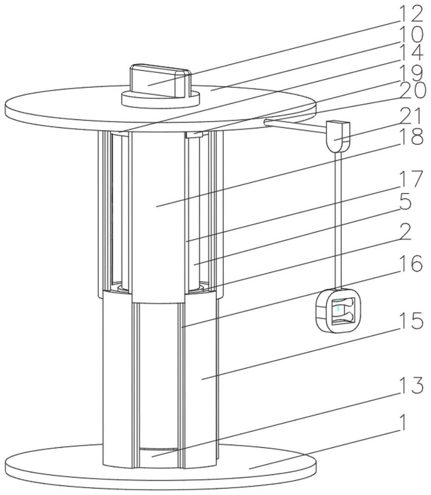
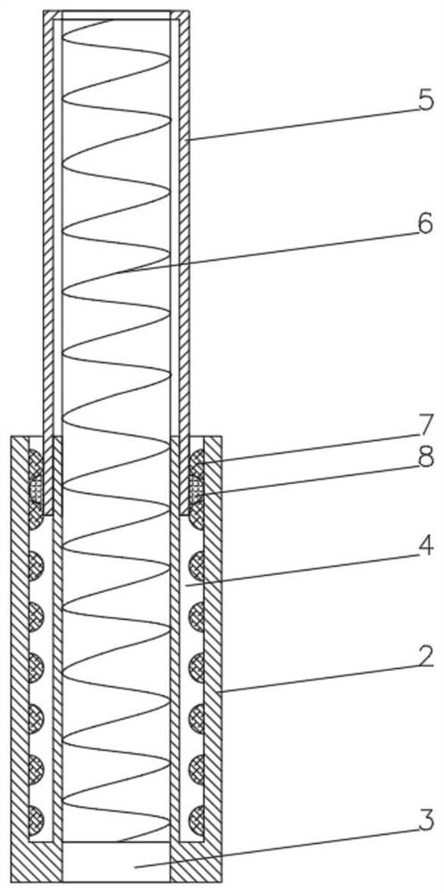
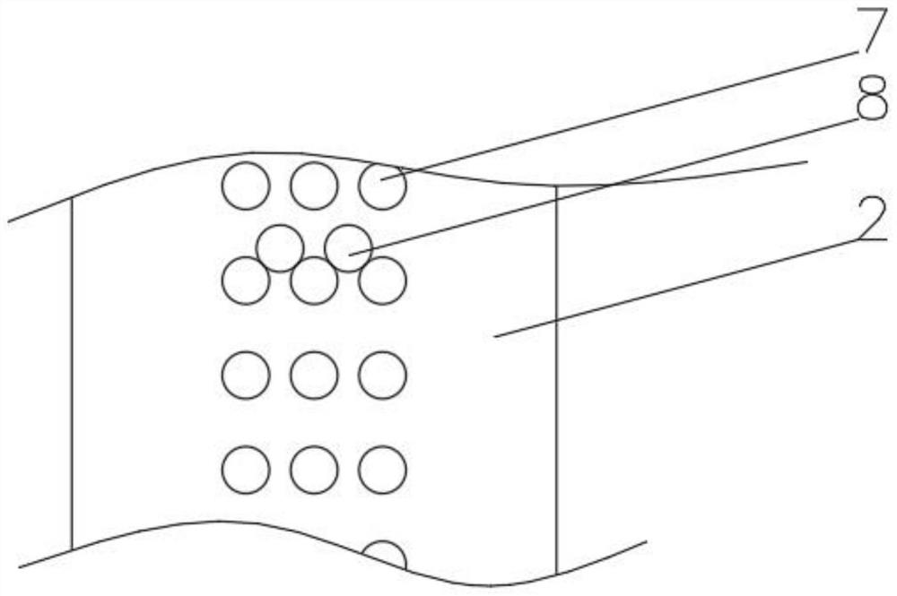
[0034] see Figure 1-4, the present invention provides a technical solution: a textile yarn tube, including a lower baffle 1, the top of the lower baffle 1 penetrates and is fixedly connected with a lower fixing column 2, and the top of the lower fixing column 2 is provided with a fixing through hole 3, and the lower fixing The top part of the column 2 located outside the fixed through hole 3 is provided with an annular groove 4, the inner wall of the annular groove 4 is slidably connected to the upper sleeve 5, and the bottom of the inner wall of the lower sleeve 2 is fixedly connected to the locking spring 6, and the top of the locking spring 6 extends to the upper The inside of the sleeve 5 is fixedly connected with the inner wall of the upper sleeve 5, the inner wall of the lower sleeve 2 is fixedly connected with the limit ball block group 7, and the part around the bottom of the upper sleeve 5 that matches the position of the limit ball block group 7 is fixed A fixed bal...
Embodiment 2
[0036] see Figure 1-5 On the basis of Embodiment 1, the present invention provides a technical solution: the buckle device 19 includes a buckle seat 191, one side of the buckle seat 191 is provided with a buckle groove 192, and one side of the inner wall of the buckle groove 192 is fixedly connected with a buckle Buckle spring 193, the buckle 194 is fixedly connected to one end of the buckle spring 193 away from the inner wall of the buckle groove 192, and the top of the buckle seat 194 is provided with a sliding hole 195 at the top of the buckle groove 192, and the top of the buckle 194 is fixedly connected with a sliding hole 194. Buckle 196, the top of the slider 196 runs through the slide hole 195 and extends to the outside of the slide hole 195. The end of the buckle 194 away from the buckle spring 193 is provided with a pressure groove 197. When winding the yarn, slide the slider 196, and the slider 196 drives Buckle 194 moves, and buckle 194 moves and compresses buckle...
Embodiment 3
[0038] see Figure 1-6 On the basis of Embodiment 1, the present invention provides a technical solution: the protective device 21 includes a telescopic rod 211, one end of the telescopic rod 211 is fixedly connected to a spring seat 212, and the bottom of the spring seat 212 is provided with a spring groove 213, and the inner wall of the spring groove 213 passes through The rotating bolt is rotatably connected with a rotating rod 214, and the parts on both sides of the rotating rod 214 in the spring groove 213 are fixedly connected with a protective spring 215, and the end of the protective spring 215 away from the inner wall of the spring groove 213 is fixedly connected with a pressing plate 216, and the rotating rod 214 is away from the spring One end of the groove 213 is fixedly connected with a guide ring 217, and the top and bottom of both sides of the guide ring 217 inner wall are rotatably connected with a protective collar 218. When unwinding, one end of the yarn passe...
PUM
 Abstract
Description
Claims
Application Information
 - R&D Engineer
- R&D Manager
- IP Professional
- Industry Leading Data Capabilities
- Powerful AI technology
- Patent DNA Extraction
Browse by: Latest US Patents, China's latest patents, Technical Efficacy Thesaurus, Application Domain, Technology Topic.
© 2024 PatSnap. All rights reserved.Legal|Privacy policy|Modern Slavery Act Transparency Statement|Sitemap