
Steel plate waterstop lifting conveying device

A steel plate waterstop, lifting and conveying technology, applied in the direction of lifting device, lifting frame, conveyor, etc., can solve the problems of large space occupied by the steel plate waterstop, thin thickness of the steel plate waterstop, blockage of conveying and other problems, and achieve the goal of transportation. Smooth process, reduce material loss, avoid deformation effect

Inactive Publication Date: 2021-03-12
龙岩市企信工业设计有限公司
View PDF0 Cites 0 Cited by
  • Summary
  • Abstract
  • Description
  • Claims
  • Application Information

AI Technical Summary

Problems solved by technology

[0003] The carrying capacity of the cargo elevator in the project is limited. When the goods such as cement carts are lifted and transported internally in turn, the steel plate waterstop takes up a lot of space, and it is difficult to carry them together with cement carts and other goods. After the lifting and conveying is completed, the steel plate waterstop Often stacked at the front end of the import and export, it is easy to cause blockage and affect the transportation of other items, and the crane is used for transportation in the engineering project, the thickness of the steel plate waterstop is thin, and the steel plate is easy to bend and deform during the lifting process, which affects the use

Method used


Image

  • Steel plate waterstop lifting conveying device
  • Steel plate waterstop lifting conveying device
  • Steel plate waterstop lifting conveying device

Examples


Embodiment Construction

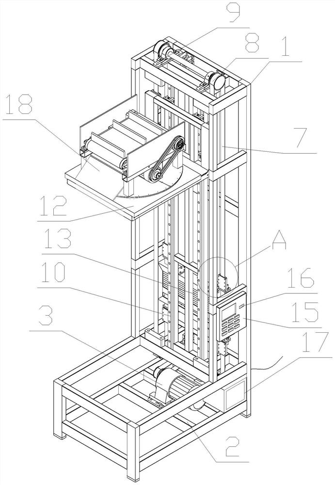
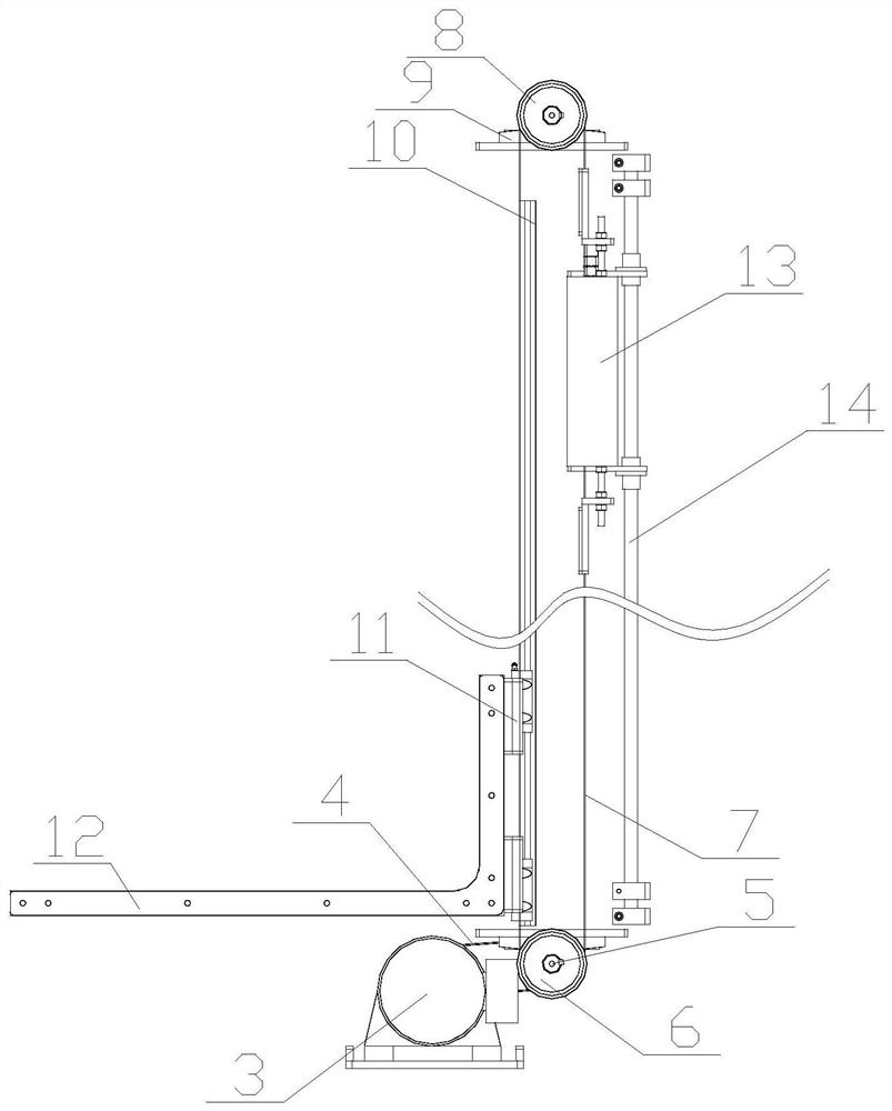
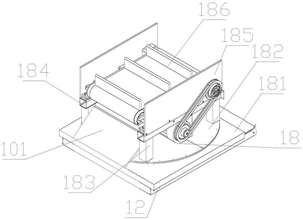
[0025] The following will be combined with Figure 1-7 The present invention is described in detail, and the technical solutions in the embodiments of the present invention are clearly and completely described. Apparently, the described embodiments are only some of the embodiments of the present invention, not all of them. Based on the embodiments of the present invention, all other embodiments obtained by persons of ordinary skill in the art without making creative efforts belong to the protection scope of the present invention.

[0026] The present invention provides a lifting and conveying device for a steel plate waterstop through improvement, including a conveying device body 1, a support frame 2, a motor 3, a belt transmission mechanism 4, a rotating shaft 5, a runner 6, a belt 7, and a second runner 8 , shaft seat 9, slide rail 10, slider 11, support frame 12, counterweight 13, guide rod 14, control panel 15, microcontroller 16, power supply unit 17 and multi-directiona...


PUM

PropertyMeasurementUnit
Heightaaaaaaaaaa

Abstract

The invention discloses a steel plate waterstop lifting conveying device. The device structurally comprises a conveying device body, a second motor at the bottom end of a supporting frame at the innerside of the lifting conveying device operates, a second rotating shaft rotates through a chain transmission mechanism, and the top end face of the second rotating shaft is fixedly connected with a rotating disc. The second rotating shaft rotates to drive a rotating disc at the top to rotate, three-direction rotation of the front end, the left end and the right end is achieved, a steel plate waterstop at the top end is conveyed to the orientation of multiple directions through an electric rotating disc, and unnecessary labor losses brought to constructors due to the fact that steel plate waterstops are stacked together when conveyed to designated positions are avoided. A third motor drives a first roller to rotate through a second belt transmission mechanism, the first roller drives a second roller to rotate through a conveying belt, the conveying belt rotates at the outer sides of the first roller and the second roller, the conveying belt rotates to output the steel plate waterstop atthe inner side of the top end to the front end, and the device has the advantages that the conveying process is stable, deformation of the steel plate waterstop due to stress in the lifting process is avoided, and material losses are reduced.

Description

technical field [0001] The invention relates to the related field of conveying devices, in particular to a lifting and conveying device for steel plate waterstops. Background technique [0002] The steel plate waterstop is to pre-embed a 300mmx3mm steel plate when pouring the lower concrete, of which the upper part of 10-15cm is exposed outside, and pour this part of the steel plate together when pouring the concrete next time. The hose is often transported by a common crane or by a freight elevator. [0003] The carrying capacity of the cargo elevator in the project is limited. When the goods such as cement carts are lifted and transported internally in turn, the steel plate waterstop takes up a lot of space, and it is difficult to carry them together with cement carts and other goods. After the lifting and conveying is completed, the steel plate waterstop Often stacked at the front end of the import and export, it is easy to cause blockage and affect the transportation of...

Claims


Application Information

Patent Timeline
IPC IPC(8): B66F7/02B66F7/28B65G15/22B65G15/58B65G29/00B65G47/44E04G21/16
CPCB65G15/22B65G15/58B65G29/00B65G47/44B66F7/02B66F7/28E04G21/162
Inventor 蓝信义
Owner 龙岩市企信工业设计有限公司
Learn More