
Oil-water separation structure for valve and implementation method thereof

A technology for oil-water separation and valves, applied in separation methods, valve housing structures, liquid separation, etc., can solve problems such as pollution, valves that do not have the function of oil-water separation, and oil-water mixtures that are not easy to separate and then discharged.

Inactive Publication Date: 2021-03-12
徐小林
View PDF0 Cites 0 Cited by
  • Summary
  • Abstract
  • Description
  • Claims
  • Application Information

AI Technical Summary

Problems solved by technology

[0003] Existing valves generally do not have the function of oil-water separation. When in use, the oil-water mixture is discharged into the external water, which is easy to cause pollution, and the imported oil-water mixture is generally not easy to separate and then discharged.

Method used


Image

  • Oil-water separation structure for valve and implementation method thereof
  • Oil-water separation structure for valve and implementation method thereof
  • Oil-water separation structure for valve and implementation method thereof

Examples


Embodiment approach

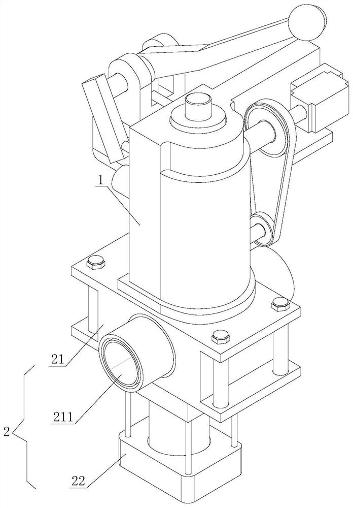
[0038] In order to better demonstrate the implementation process of the oil-water separation structure for the valve, this embodiment now proposes an implementation method for the oil-water separation structure for the valve, including the following steps:

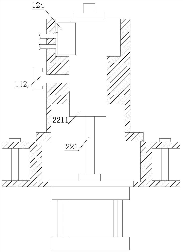
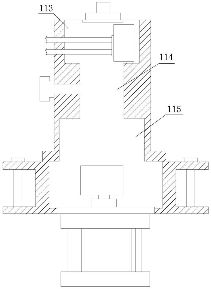
[0039] Step 1: Open the rubber sealing plug 1111 and pour the oil-water mixture into the inner cavity of the valve body 11 through the liquid injection port 111, start the explosion-proof motor 13 at the same time, use the explosion-proof motor 13 to drive the rotating shaft 131 and drive the main drive wheel 141 to rotate at a high speed ;

[0040] Step 2: The main driving wheel 141 rotates at a high speed and drives the secondary driving wheel 142 to rotate synchronously through the roller belt 1411 connected to it, and the secondary rotating rod 1421 connected to one end of the secondary driving wheel 142 drives the folding roller knife 14211 to flow into the The oil-water mixture in the separation working chamber 115 r...


PUM


Abstract

The invention discloses an oil-water separation structure for a valve and further discloses an implementation method of the oil-water separation structure for the valve. The oil-water separation structure for the valve comprises a main oil-water separation mechanism and a bearing and water discharging mechanism, and the bearing and water discharging mechanism is installed at the bottom end of themain oil-water separation mechanism. According to the oil-water separation structure for the valve, after oil-water mixed liquid is poured into the inner cavity of the valve body through a liquid injection port, an explosion-proof motor is used for driving a rotating shaft and driving a driving wheel to rotate at a high speed, a driven rotation rod connected with one end of a driven wheel drives bent type roller cutters to rotate the oil-water mixed liquid flowing into a separation working chamber at a high speed, and different centrifugal forces is generated so as to separate oil from water;since the density of the oil is smaller than that of the water, the separated oil is discharged into the upper end of the inner cavity of the valve body, and the water flows into an inner cavity of abearing outer frame communicated with the valve body. Compared with a common valve, the valve has the oil-water separation function, and the situation that when the valve is used, since introduced oiland water are mixed and cannot be separated, the oil and water mixture is discharged into outside water and causes pollution can be prevented.

Description

technical field [0001] The invention relates to the technical field of oil-water separation structures, in particular to an oil-water separation structure for valves and an implementation method thereof. Background technique [0002] Oil-water separation is mainly based on the density difference or chemical properties of water and oil, using the principle of gravity sedimentation or other physical and chemical reactions to remove impurities or complete the separation of oil and water. Due to the different relative densities of oil, gas, and water, a certain oil-water mixture will form a certain proportion of oil, gas, and water phases when the system is in equilibrium under a certain pressure and temperature. The oil-water separator is an instrument that separates oil and water. In terms of mechanism, it is mainly divided into water-in-oil separator and oil-in-water separator; in terms of use, it is mainly divided into industrial-grade oil-water separator, commercial oil-wat...

Claims


Application Information

Patent Timeline
IPC IPC(8): F16K11/20F16K27/02F16K31/122B01D17/038F04B9/12F04B9/10F04B9/14
CPCB01D17/0217F04B9/10F04B9/12F04B9/14F16K11/20F16K27/0263F16K31/1225
Inventor 徐小林
Owner 徐小林
Learn More