
Device capable of automatically treating steam engine exhaust pollution

An automatic processing and steam engine technology, which is applied in the field of steam engines, can solve the problems of slowing down the cooling rate of steam, full combustion of unfavorable fuels, air pollution, etc., to prevent the discharge of harmful gases, improve energy utilization efficiency, and prevent the accumulation of dirt Effect

Inactive Publication Date: 2021-03-12
DONGYANG NARUI STEAM ENGINE EQUIP TECH CO LTD
View PDF0 Cites 2 Cited by
  • Summary
  • Abstract
  • Description
  • Claims
  • Application Information

AI Technical Summary

Problems solved by technology

[0002] The steam engine has brought rapid development to human progress. When the steam engine boils water to generate high-pressure steam, it needs to use wood, coal, oil or natural gas as a heat source. Insufficient combustion of fuel will produce a large amount of harmful gas and fuel flying. The discharge of chips is not conducive to the full combustion of fuel, and it will also cause serious pollution to the air, which is not conducive to the protection of the environment. When the steam engine is running, it is necessary to slow down the cooling rate of the steam in order to improve the utilization rate of energy. The prior art There are also certain defects, and the optimization of the steam engine has not been realized. A device that can automatically deal with the exhaust pollution of the steam engine set forth in the present invention can solve the above problems

Method used


Image

  • Device capable of automatically treating steam engine exhaust pollution
  • Device capable of automatically treating steam engine exhaust pollution
  • Device capable of automatically treating steam engine exhaust pollution

Examples


Embodiment Construction

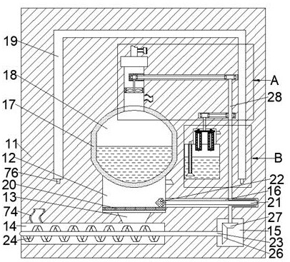
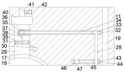
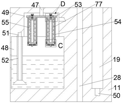
[0019] Combine below Figure 1-6 The present invention is described in detail, wherein, for the convenience of description, the orientations mentioned below are defined as follows: figure 1 The up, down, left, right, front and back directions of the projection relationship itself are the same.

[0020]A device capable of automatically treating exhaust pollution from a steam engine according to the present invention includes a body 11, an incineration chamber 12 is provided inside the body 11, and the incineration chamber 12 can carry out material combustion. The lower side of the incineration chamber 12 is The wall is communicated with a reciprocating push chamber 16 extending to the right. The left end of the body 11 on the lower side of the incineration chamber 12 is connected with a slag discharge chamber 14 extending to the right. The slag discharge chamber 14 on the right side The body 11 is provided with a bevel gear chamber 15, and a slag discharge hole 13 is connected...


PUM


Abstract

The invention discloses a device capable of automatically treating steam engine exhaust pollution. The device comprises a machine body, an incineration cavity is formed in the machine body, the incineration cavity can be used for conducting substance combustion, the right wall face of the lower side of the incineration cavity is provided with a reciprocating pushing cavity extending rightwards ina communicating mode, and the position, on the lower side of the incineration cavity, of the left end face of the machine body is provided with a furnace slag discharging cavity extending rightwards in a communicating mode. According to the device, waste gas generated after combustion of a steam engine is treated in time so that harmful gas can be effectively prevented from being exhausted; meanwhile, by means of air pressure generated during steam circulation, dirt generated in combustion waste gas can be adsorbed and discharged in time, so that the dirt generated in the combustion waste gasis effectively prevented from being accumulated, and then the overall self-cleaning function of the steam engine can be achieved; and meanwhile, the device can form a temperature isolation belt by means of the treated waste gas, so that the steam temperature lowering speed is effectively decreased, and the energy utilization efficiency of the steam engine is improved.

Description

technical field [0001] The invention relates to the field of steam engines, in particular to a device capable of automatically treating the exhaust pollution of steam engines. Background technique [0002] The steam engine has brought rapid development to human progress. When the steam engine boils water to generate high-pressure steam, it needs to use wood, coal, oil or natural gas as a heat source. Insufficient combustion of fuel will produce a large amount of harmful gas and fuel flying. The discharge of chips is not conducive to the full combustion of fuel, and it will also cause serious pollution to the air, which is not conducive to the protection of the environment. When the steam engine is running, it is necessary to slow down the cooling rate of the steam in order to improve the utilization rate of energy. The prior art There are still certain defects, and the optimization of the steam engine has not been realized. A device capable of automatically treating the exha...

Claims


Application Information

Patent Timeline
Patent Type & Authority Applications(China)
IPC IPC(8): F23J15/04F22B1/22F23G5/44F23G5/46F23J1/00
CPCF22B1/22F23G5/44F23G5/46F23J1/00F23J15/04F23J2217/50
Inventor 谢亚杰
Owner DONGYANG NARUI STEAM ENGINE EQUIP TECH CO LTD
Learn More