Heat supply systems and method based on coupling phase change

A heating system and phase change technology, applied in the field of heating systems based on coupled phase change, can solve the problems of aggravating the fluctuation of the heating network, the instability of renewable energy, and the impact of stable operation, so as to reduce the energy consumption of the system and be easy to control. , the effect of strong practicability

Pending Publication Date: 2021-03-12
华能安阳热电有限责任公司 +1
View PDF0 Cites 0 Cited by
  • Summary
  • Abstract
  • Description
  • Claims
  • Application Information

AI Technical Summary

Problems solved by technology

However, due to the intermittency and instability of renewable energy, its direct combination with the heating ne

Method used


Image

  • Heat supply systems and method based on coupling phase change
  • Heat supply systems and method based on coupling phase change

Examples


Embodiment 1

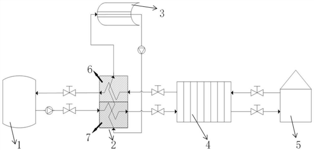
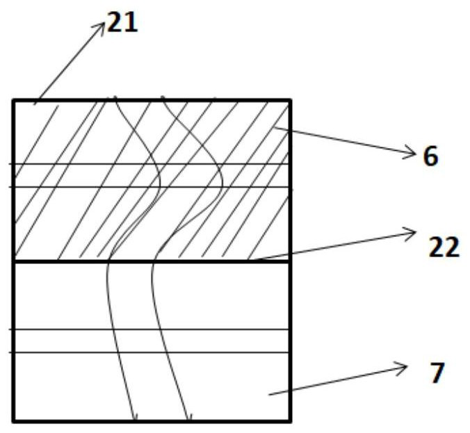
[0033] A heating system based on coupled phase transitions, such as figure 1 As shown, it includes a first water circulation loop composed of sequentially connected heat source 1, heat station 4 and heat user 5, the inlet pipeline of each heat station 4 is connected with a heat storage device 2, and the heat storage device 2 is connected with a heater 3, The outlet end of the heat station 4 is connected with the heat user 5; as figure 2 As shown, the heat storage device 2 includes a box body 21, and a partition plate 22 is arranged in the middle of the box body 21. The partition plate 22 divides the interior of the box body 21 into two areas, which are respectively the first heat preservation area 6 and the second heat preservation area. Heat preservation zone 7, the first heat preservation zone 6 and the second heat preservation zone 7 are all provided with inlet port and outlet port; They are respectively connected to the heat station 4 and the heat source 1; the first hea...

Embodiment 2

[0035] Except for the following content, all the other contents are the same as in Example 1.

[0036] The inlet port of the second thermal insulation zone 7 is connected with the outlet port of heat source 1, and the outlet port of the second thermal insulation zone 7 is connected with the inlet port of thermal station 4; The inlet port of the first thermal insulation zone 6 is connected with the outlet port of thermal station 4, The outlet end of the first heat preservation zone 6 is connected with the inlet end of the heat source 1 . Valves are arranged on the pipelines connected among the heat source 1 , the heater 3 , the heat station 4 , the heat user 5 , the first heat preservation zone 6 and the second heat preservation zone 7 . The low-temperature phase-change material is paraffin; the high-temperature phase-change material is an aqueous solution of inorganic salt.

Embodiment 3

[0038] Except for the following content, all the other contents are the same as in Example 1.

[0039] The heater 3 is installed above the heat storage device 2 . In the heat storage device 2 , the first heat preservation zone 6 is located on top of the second heat preservation zone 7 . In the water circulation loop, the outlet end of the first heat preservation zone 6 is connected to the inlet end of the heater 3 , and the outlet end of the heater 3 is connected to the inlet end of the second heat preservation zone 7 . The heater 3 is a solar heater.

[0040] A heating method based on the above-mentioned heating system, specifically:

[0041] The first water circulation loop starts to work, the valve at the outlet of heat source 1 is opened, the hot water in heat source 1 flows into the second heat preservation zone 7, and flows into the heat station 4 through the pipeline in the second heat preservation zone 7, and then flows to the heat station 4 through the heat power st...


PUM


Abstract

The invention discloses heat supply systems and a heat supply method based on coupling phase change, and belongs to the field of civil heat supply. The heat supply systems comprise the civil heat supply system and the solar heating system. The heat supply systems comprise a first water circulation loop composed of a heat source, a thermal station and a heat user which are connected in sequence, the heat storage device comprises a box body, a partition plate is arranged in the middle of the box body and divides the interior of the box body into a first heat preservation area and a second heat preservation area, and the first heat preservation area and the second heat preservation area are each provided with an inlet end and an outlet end; The two ends of the first heat preservation area areconnected with a heating station and a heat source correspondingly. The two ends of the second heat preservation area are connected with the heating station and the heat source correspondingly. and the first heat preservation area, the heater and the second heat preservation area form a second water circulation loop. The high temperature of the second heat preservation area is kept through the second water circulation loop, and therefore it is guaranteed that water entering the thermal station is within the high temperature range. Phase-change heat storage and a solar heating system are combined, the characteristics of intermittency and instability of solar energy can be stabilized, the phase-change material can reach a phase-change area more quickly, and energy consumption is reduced.

Description

technical field [0001] The invention belongs to the field of civil heat supply, and relates to a heat supply system and method based on coupled phase transitions. Background technique [0002] At present, most of the residential heat supply adopts the method of direct supply throughout the day, but for the vast majority of heat users, they do not stay at home all day, and the uninterrupted heat supply when there is no one is bound to cause energy waste. The way is the development trend of heating. Heat metering is a heat supply operation method that measures and charges users according to the actual heat consumed by users. Heat users can adjust the heat supply according to their own needs, and charge for the actual heat consumption of heat users, which reduces the heat consumption costs of users and reduces system energy consumption. However, the heat metering method will cause problems for the operation of the heating network. The frequent opening and closing of valves b...

Claims


Application Information

Patent Timeline
IPC IPC(8): F24D11/00F24D19/00
CPCF24D11/002F24D19/0002Y02B10/20
Inventor 白烨赵树春曲志忠姚国鹏王忠权张瑞文孔德伟和占林王保民黄伟姜春洋姜向松李旭周贤
Owner 华能安阳热电有限责任公司
Why Eureka
Try Eureka