Eureka AIR delivers breakthrough ideas for toughest innovation challenges, trusted by R&D personnel around the world.

AC low-voltage power distribution cabinet for power plant

A technology of low-voltage electric power and power distribution cabinets, which is applied to the substation/power distribution device shell, electrical components, substation/switch layout details, etc., which can solve the problems of reduced work efficiency, error-prone maintenance, and inconvenient maintenance of power distribution cabinets, etc. Achieve the effects of increasing space utilization, increasing heat dissipation, and increasing convenience

Inactive Publication Date: 2021-03-12
深圳利朋技术研发有限公司
View PDF0 Cites 0 Cited by
  • Summary
  • Abstract
  • Description
  • Claims
  • Application Information

AI Technical Summary

Problems solved by technology

[0003] The power distribution cabinet is made of steel and is used to protect the normal operation of components. There are several partitions in the power distribution cabinet. The partitions are provided with grooves for placing components. When the components are damaged and need to be repaired, the maintenance personnel can only open the cabinet door to check and maintain the components in the power distribution cabinet. Due to the limited field of vision when inspecting the internal conditions of the power distribution cabinet, the maintenance personnel cannot comprehensively inspect the components. Inspection of damaged components can easily lead to inaccurate judgments, and it is easy to make mistakes during the maintenance process, which is time-consuming and labor-intensive, reducing work efficiency. Very inconvenient for maintenance

Method used


Image

  • AC low-voltage power distribution cabinet for power plant
  • AC low-voltage power distribution cabinet for power plant
  • AC low-voltage power distribution cabinet for power plant

Examples


Embodiment Construction

[0028] The following will clearly and completely describe the technical solutions in the embodiments of the present invention with reference to the accompanying drawings in the embodiments of the present invention. Obviously, the described embodiments are only some, not all, embodiments of the present invention. Based on the embodiments of the present invention, all other embodiments obtained by persons of ordinary skill in the art without making creative efforts belong to the protection scope of the present invention.

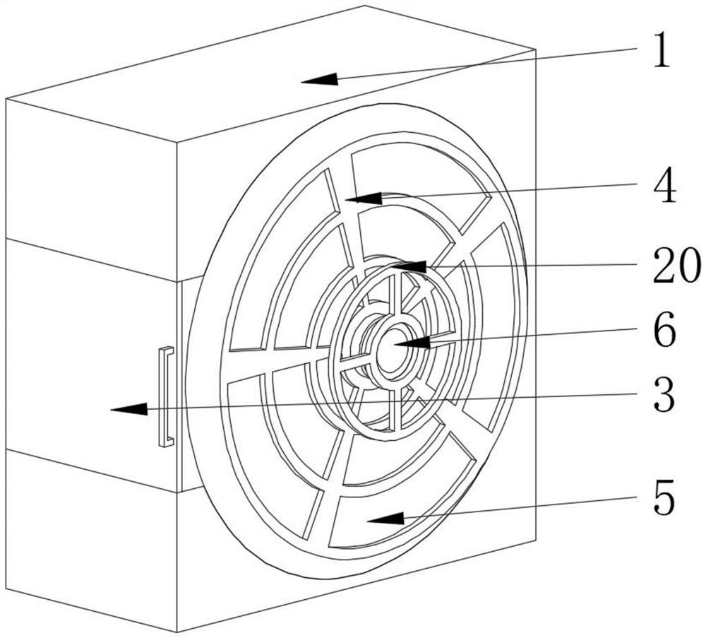
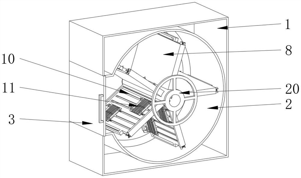
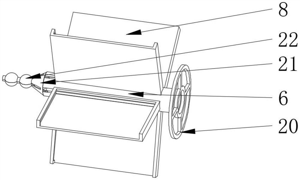
[0029] see Figure 1-10 , an AC low-voltage power distribution cabinet for a power plant, including a casing 1, an inner cavity 2 is fixedly installed inside the outer casing 1, a box door 3 is movably installed on one side of the inner cavity 2, and a box door 3 is fixedly installed on both sides of the inner cavity 2 Cooling hole 4, the inner side of cooling hole 4 is equipped with filter screen 5, through the both sides of housing 1 are fixedly installed wi...


PUM


Abstract

The invention relates to the technical field of power distribution cabinets, and discloses an AC low-voltage power distribution cabinet for a power plant. The AC low-voltage power distribution cabinetcomprises a housing, an inner cavity is fixedly installed in the housing, and a box door is movably installed at one side of the inner cavity. Heat dissipation holes are fixedly installed at the twosides of the inner cavity, and filter screens are movably installed at the inner sides of the heat dissipation holes. A central shaft is movably installed in the middle of the inner cavity, and a wireinlet groove is formed in the middle of the central shaft. According to the alternating-current low-voltage power distribution cabinet for the power plant, the lower plates are movably mounted through the clamping pieces and the wire inlet grooves, the upper plates are movably mounted on the lower plates, and the mounting plates are movably mounted on the upper plates, so that electrical apparatus elements are conveniently fixed on the lower plates; the five lower plates are mounted in a pentagon shape, so that the internal space utilization rate of the device is increased; and each lower plate can be conveniently and obliquely displayed when passing through the box door, so that the electrical elements on the lower plates can be conveniently overhauled, and the overhauling convenience ofthe device is improved.

Description

technical field [0001] The invention relates to the technical field of power distribution cabinets, in particular to an AC low-voltage power distribution cabinet for power plants. Background technique [0002] In the contemporary power system, the power distribution cabinet is the most common power supply equipment with a wide range of applications. It is the final equipment of the power distribution system. The use of the power distribution cabinet can ensure the safe operation of the power system and promote its sustainable development. , the power distribution cabinet (box) is divided into power distribution cabinet (box), lighting distribution cabinet (box) and metering cabinet (box), each of which is assembled from various types of electronic components. The location and demand of the environment should be precisely configured. The power distribution cabinet is used in the occasions where the load is relatively scattered and there are few circuits; the motor control cen...

Claims


Application Information

Patent Timeline
IPC IPC(8): H02B1/30H02B1/56H02B1/28H02B1/20
CPCH02B1/20H02B1/28H02B1/30H02B1/565
Inventor 不公告发明人
Owner 深圳利朋技术研发有限公司
Why Eureka
Eureka Blog
Learn More