
Micro-fluidic chip

A microfluidic chip and microfluidic channel technology, applied in the field of microfluidics, can solve the problems of poor repeatability and low detection accuracy of microfluidic chips, and achieve improved detection accuracy, reduced volume, and good mixing effect Effect

Active Publication Date: 2021-03-16
合肥中科国腾生物科技有限公司
View PDF9 Cites 0 Cited by
  • Summary
  • Abstract
  • Description
  • Claims
  • Application Information

AI Technical Summary

Problems solved by technology

[0005] The main purpose of the present invention is to provide a microfluidic chip, which aims to solve the problems of low detection accuracy and poor repeatability of existing microfluidic chips

Method used


Image

  • Micro-fluidic chip
  • Micro-fluidic chip
  • Micro-fluidic chip

Examples


Embodiment

[0092] Step 1: Add the sample to be tested

[0093] Open the sealing cover of the sample inlet 101, manually add the sample to be tested into the sample chamber 201, close the sealing cover tightly, and insert the microfluidic chip 10 into the detection instrument in standby state.

[0094] Step 2: Sample dilution and filtration

[0095] Run the instrument, open the first air outlet 103 of the reaction waste liquid storage chamber 211, close the second air outlet 105 of the detection waste liquid storage chamber 210, input a certain amount of air from the sample inlet 101 to pressurize the sample chamber 201, and drive the sample reagent From the sample chamber 201 to the sample mixing flow channel 203; at the same time, the reagent pressure rod is inserted into the reagent pressure rod inlet 102 to pressurize the diluent reagent capsule 301 in the diluent chamber 202, driving a quantitative diluent into the sample mixing flow channel 203, Mix with the sample; continue to inp...


PUM


Abstract

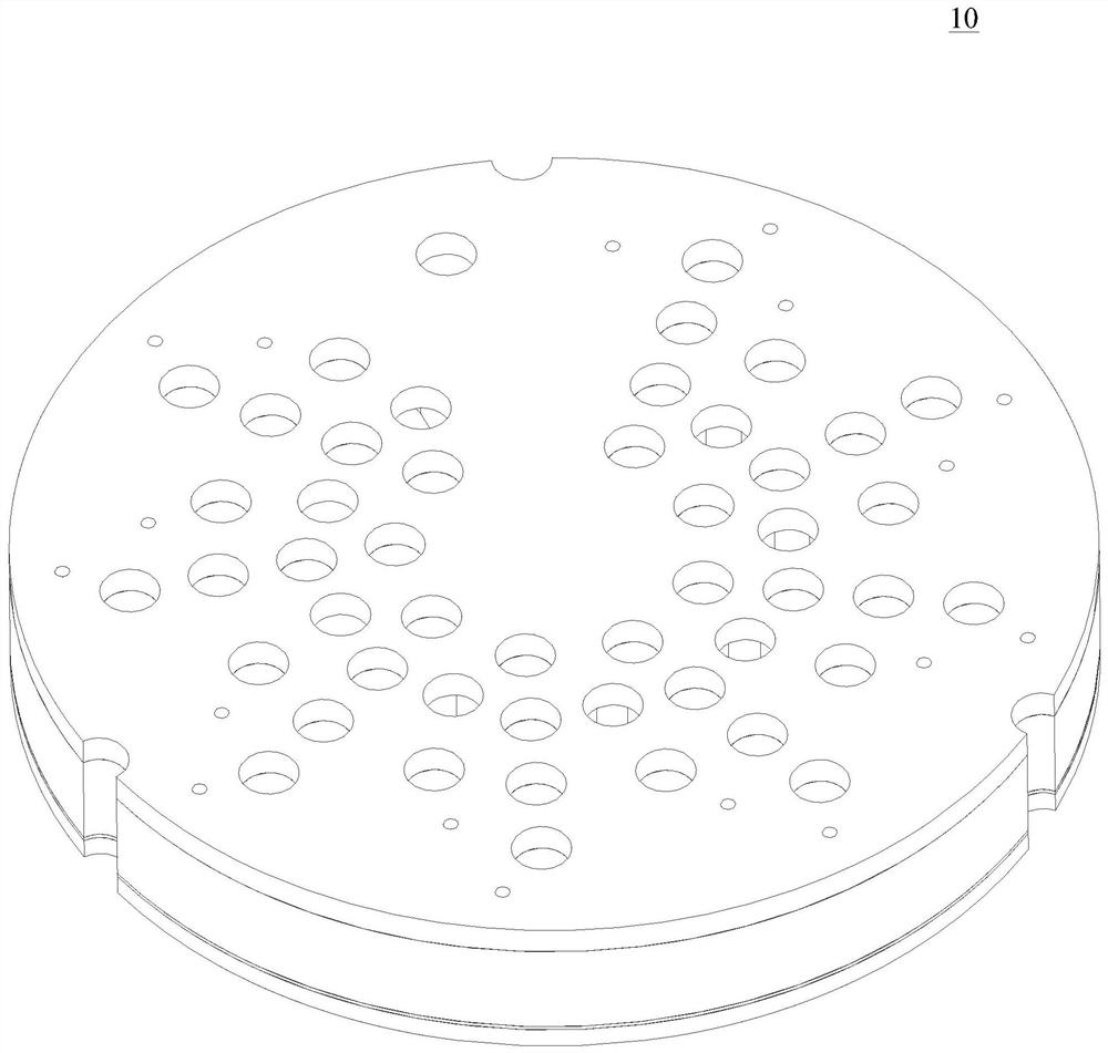
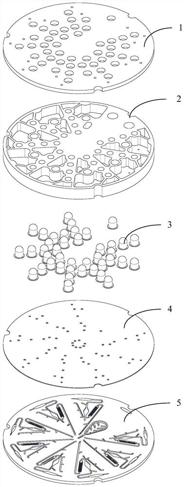
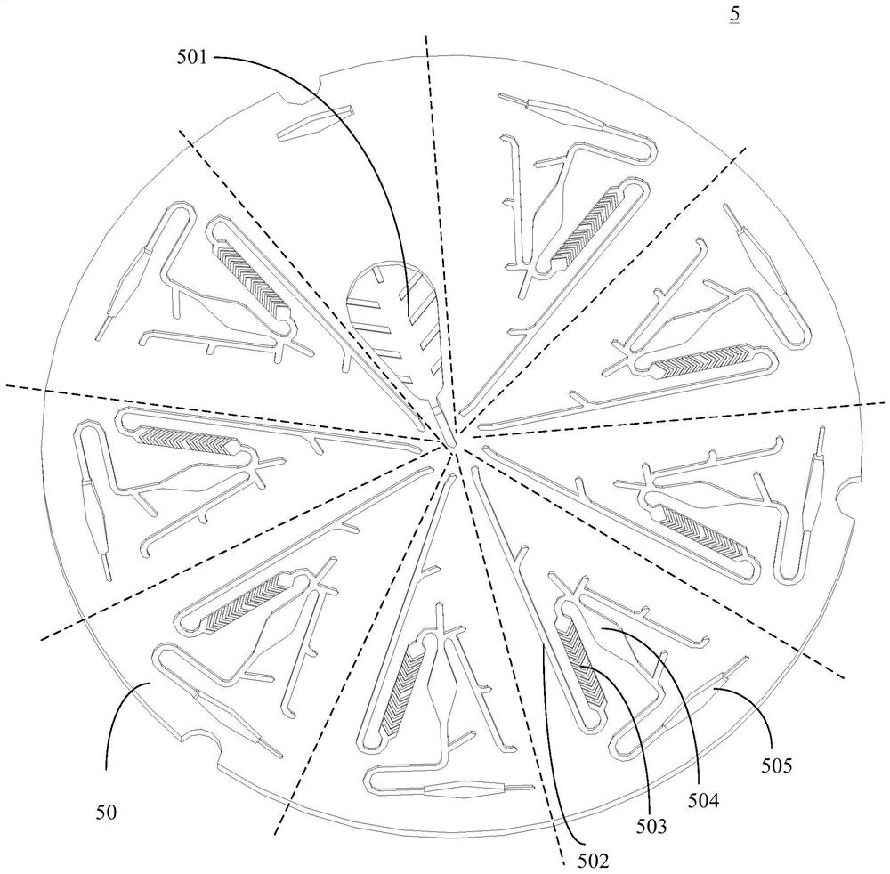
The invention provides a micro-fluidic chip which comprises a sample cavity and at least one reaction detection unit communicated with the sample cavity, the at least one reaction detection unit is arranged on a bottom plate, and reagents required by the at least one reaction detection unit are stored in a storage cavity of a reagent storage cavity plate. The storage cavity is communicated with the at least one reaction detection unit through a first one-way through hole; the first power source is used for driving the sample to flow to the reaction detection unit, and the second power source is used for driving the reagent in the storage cavity to flow to the reaction detection unit. According to the technical scheme, the micro-fluidic chip is of a multi-layer structure, the reagents required by the reaction detection unit and the reaction detection unit are designed on different layers, and the sample and the reaction reagent are added into the reaction detection unit through different power sources respectively, so that the mixing effect of the sample and the reaction reagent is better, the detection precision is improved, and the length of the flow channel can be reduced, the size of the micro-fluidic chip is reduced, and the cost is saved.

Description

technical field [0001] The invention relates to the field of microfluidic technology, in particular to a microfluidic chip. Background technique [0002] At present, the common problems of analytical instruments used for clinical diagnosis are that the instruments are bulky, expensive, require high operating skills, run for a long time, consume a large amount of samples and reagents, and there is a risk of cross-contamination of samples and reagents. [0003] Microfluidic chips are currently a hot spot in the development of Miniaturized Total Analysis Systems. Microfluidic chips integrate sample detection in biological, chemical, medical and other analysis processes on a tiny chip. Microfluidic chips have the characteristics of controllable liquid flow, minimal consumption of samples and reagents, and fast analysis speed. Microfluidic chips can effectively support the advantages of miniaturization of analytical instruments, integration of functional units, closed reaction ...

Claims


Application Information

Patent Timeline
Patent Type & Authority Applications(China)
IPC IPC(8): B01L3/00G01N33/53G01N33/543G01N33/58
CPCB01L3/5027G01N33/5304G01N33/581G01N33/54326G01N33/582B01L2200/10
Inventor 金腾川丁卫平成斌李清宁
Owner 合肥中科国腾生物科技有限公司
Learn More