

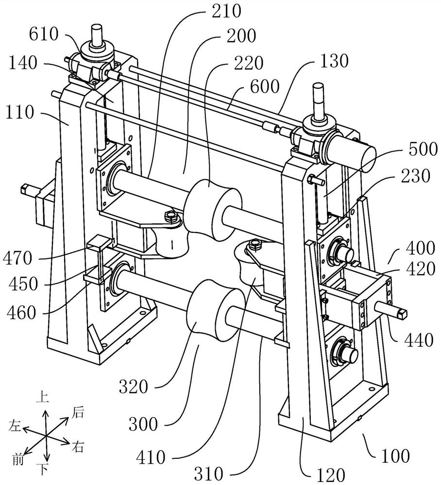
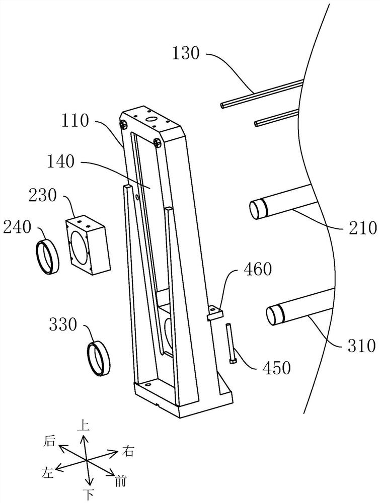
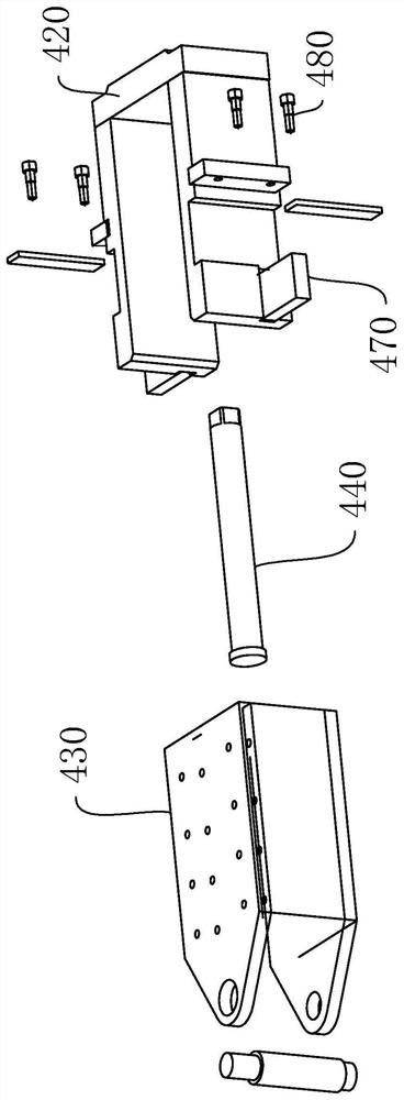
Vertical frame forming structure of stainless steel tube making machine
A technology of forming structure and pipe making machine, applied in metal rolling stands, metal rolling, manufacturing tools, etc., can solve the problems of low automation production, unreasonable force on die rolls, and short service life, etc. To achieve the effect of reducing equipment space and material costs, reducing manual debugging workload, and reducing workers' debugging time
- Summary
- Abstract
- Description
- Claims
- Application Information
AI Technical Summary
Problems solved by technology
Method used
Image

Examples
Embodiment Construction
[0031] This part will describe the specific embodiment of the present invention in detail, and the preferred embodiment of the present invention is shown in the accompanying drawings. Each technical feature and overall technical solution of the invention, but it should not be understood as a limitation on the protection scope of the present invention.
[0032] In the description of the present invention, it should be understood that the orientation descriptions, such as up, down, front, back, left, right, etc. indicated orientations or positional relationships are based on the orientations or positional relationships shown in the drawings, and are only In order to facilitate the description of the present invention and simplify the description, it does not indicate or imply that the device or element referred to must have a specific orientation, be constructed and operated in a specific orientation, and thus should not be construed as limiting the present invention.
[0033] I...
PUM
 Abstract
Description
Claims
Application Information