Eureka AIR delivers breakthrough ideas for toughest innovation challenges, trusted by R&D personnel around the world.

Equal-angle drilling device

A drilling device and isometric technology, applied in positioning devices, clamping devices, boring/drilling and other directions, can solve the problems of many steps, time-consuming and laborious, inaccurate and other problems, achieve stable and reliable structure, improve work efficiency, The effect of a high degree of automation

Inactive Publication Date: 2021-03-16
宁波爵盛科技有限公司
View PDF0 Cites 1 Cited by
  • Summary
  • Abstract
  • Description
  • Claims
  • Application Information

AI Technical Summary

Problems solved by technology

[0002] At present, most of the peripheral punching of large steel pipes is to use a portable magnet punching machine. The lower end of the portable magnet punching machine is provided with an arc-shaped block that can be attached to a large steel pipe. The left and right ends of the arc-shaped block are symmetrical and There are magnets that slide up and down to hold the large steel pipe firmly. First, fix the large steel pipe with a clamp, and then attach the arc-shaped block of the portable magnet puncher to the outer ring of the large steel pipe, and determine the position and angle. Afterwards, the magnet slides down and sucks on the large steel pipe, so that it is fixed on the large steel pipe, and then the handle is turned by hand, so that the drill bit faces the large steel pipe to drill, and then the magnet moves up and releases the large steel pipe, and the arc block fits and moves to drill Hole machine, repeat the above steps to complete the circumferential drilling of large steel pipes, but in the above process, the staff needs to repeatedly adjust the position and angle, and repeatedly operate the portable magnet hole puncher. The steps are numerous and not accurate enough, and it is time-consuming and laborious

Method used


Image

  • Equal-angle drilling device
  • Equal-angle drilling device
  • Equal-angle drilling device

Examples


Embodiment Construction

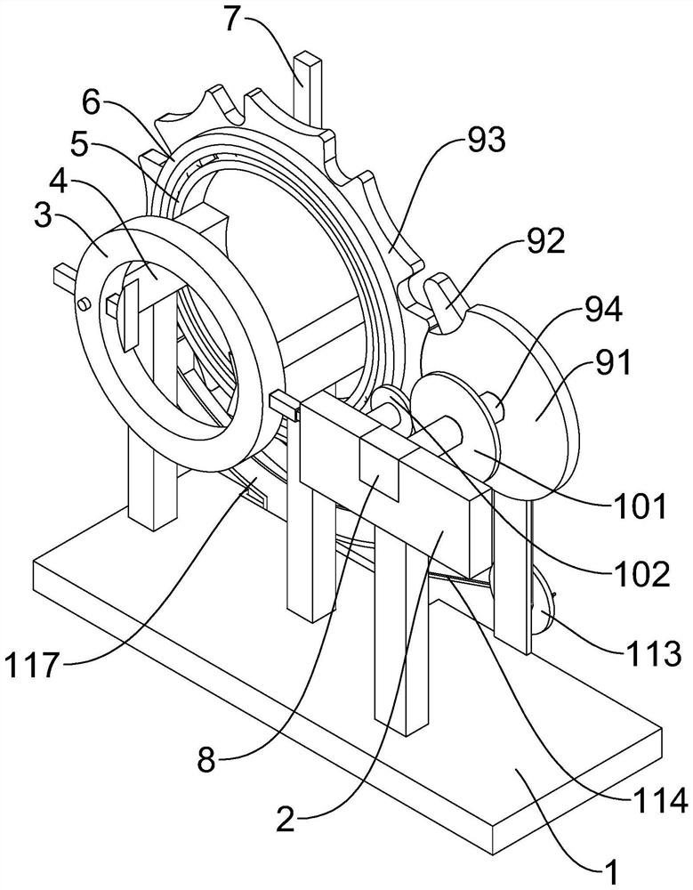
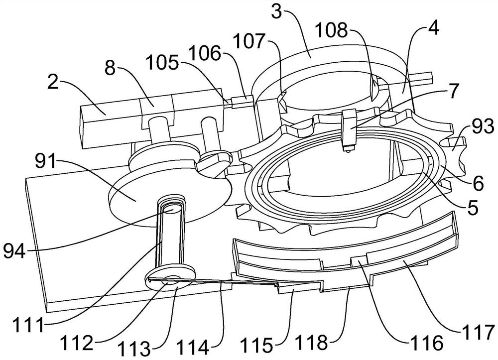
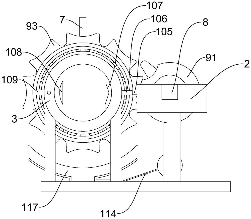
[0025] like Figure 1 to Figure 12 As shown, an equiangular drilling device includes a base 1, the left and right sides above the base 1 are respectively provided with a connecting block 4 and a fixed block 2 through brackets, and the front and rear ends of the connecting block 4 are respectively provided with a first ring 3 , bearing 5, the outer ring of bearing 5 is keyed with second annulus 6, the rear side of the second annulus 6 upper ends is provided with stepping air cylinder 7, is connected with drilling machine on the piston of stepping air cylinder 7, fixed block 2 A stepping motor 8 is provided inside, and the output shaft of the stepping motor 8 is connected with a rotating mechanism 9 for intermittently making the second annulus 6 rotate at the same angle. The clamping assembly 10 connected to the output shaft of the motor 8, the base 1 is provided with the collection assembly 11 matched with the rotating mechanism 9, the rotating mechanism 9 includes the first ro...


PUM


Abstract

The invention discloses an equal-angle drilling device. The equal-angle drilling device comprises a base, wherein a connecting block and a fixing block are arranged on the left side and the right sideabove the base through supports correspondingly, and a first circular ring and a bearing are arranged at the front end and the rear end of the connecting block correspondingly; a second circular ringis in keyed joint with the outer ring of the bearing, and a stepping air cylinder is arranged on the rear side of the upper end of the second circular ring; a drilling machine is connected to a piston of the stepping air cylinder; a stepping motor is arranged in the fixing block, and a rotating mechanism used for intermittently enabling the second circular ring to rotate by the same angle is connected to an output shaft of the stepping motor; and clamping assemblies connected with the output shaft of the stepping motor are arranged on the first circular ring and the fixing block. The equal-angle drilling device has the advantages that the structure is stable and reliable, and continuous clamping is automatically completed; in the continuous clamping process, after the second circular ringrotates by the same angle each time, drilling is conducted; a large steel pipe is automatically loosened after circumferential drilling is completed, and meanwhile waste can be collected, compressedand recycled; and the automation degree is high, and the working efficiency is improved.

Description

technical field [0001] The invention relates to a drilling device, in particular to an equiangular drilling device. Background technique [0002] At present, most of the peripheral punching of large steel pipes is to use a portable magnet punching machine. The lower end of the portable magnet punching machine is provided with an arc-shaped block that can be attached to a large steel pipe. The left and right ends of the arc-shaped block are symmetrical and There are magnets that slide up and down to hold the large steel pipe firmly. First, fix the large steel pipe with a clamp, and then attach the arc-shaped block of the portable magnet puncher to the outer ring of the large steel pipe, and determine the position and angle. Afterwards, the magnet slides down and sucks on the large steel pipe, so that it is fixed on the large steel pipe, and then the handle is turned by hand, so that the drill bit faces the large steel pipe to drill, and then the magnet moves up and releases t...

Claims


Application Information

Patent Timeline
Patent Type & Authority Applications(China)
IPC IPC(8): B23B41/00B23Q3/00B23Q16/02B23Q11/00
CPCB23B41/00B23Q3/00B23Q11/0042B23Q16/025B23Q2703/10
Inventor 不公告发明人
Owner 宁波爵盛科技有限公司
Why Eureka
Eureka Blog
Learn More