Printing forming chamber with local temperature control function and 3D printer with printing forming chamber

A technology of local temperature and molding chamber, which is applied in the field of 3D printing, can solve the problem of not being able to provide higher temperature during the printing process, achieve high heating utilization efficiency and improve heating efficiency

Pending Publication Date: 2021-03-16
MEDPRIN REGENERATIVE MEDICAL TECH
View PDF0 Cites 3 Cited by
  • Summary
  • Abstract
  • Description
  • Claims
  • Application Information

AI Technical Summary

Problems solved by technology

[0004] In order to overcome the defect that the existing 3D printer molding chamber cannot provide a higher temperatu

Method used


Image

  • Printing forming chamber with local temperature control function and 3D printer with printing forming chamber
  • Printing forming chamber with local temperature control function and 3D printer with printing forming chamber
  • Printing forming chamber with local temperature control function and 3D printer with printing forming chamber

Examples


Embodiment 1

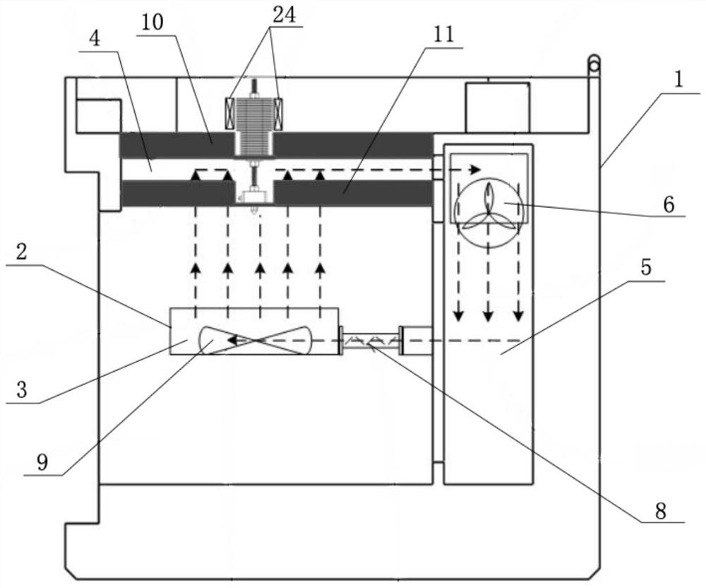
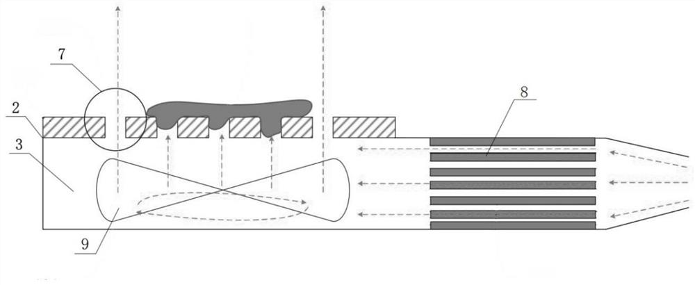
[0034] like Figure 1 to Figure 5 As shown, a printing and forming chamber with local temperature control includes an outer casing 1, a forming platform 2 arranged inside the outer casing 1, and a printing nozzle arranged above the forming platform 2, wherein the outer casing The inside of the body 1 is also provided with a hot air circulating air duct that enables the forming platform 2 to blow upward airflow that can wrap the printing model on the top surface of the forming platform 2 above the top surface; A throat 19 extending through the hot air circulation air duct to the top of the forming platform 2, connected to the nozzle 20 on the end of the throat 19 close to the forming platform 2, and passing through the throat The sprinkler heating module and the sprinkler heat dissipation module on 19 , the sprinkler heating module is located inside the hot air circulation air duct, and the sprinkler heat dissipation module is located outside the outer casing 1 . For polymer m...

Embodiment 2

[0048] A 3D printer, comprising the printing chamber with local temperature control described in Embodiment 1.


PUM


Abstract

The invention provides a printing forming chamber with a local temperature control function. The printing forming chamber comprises an outer shell, a forming platform arranged in the outer shell and aprinting spray head arranged above the forming platform, wherein a hot air circulation air duct which enables the forming platform to blow out upward airflow capable of wrapping a printing model on the top face of the forming platform towards the position above the top face of the forming platform is further arranged in the outer shell; the printing spray head comprises a throat pipe, a nozzle, aspray head heating module and a spray head heat dissipation module, wherein one end of the throat pipe penetrates the hot air circulation air duct from the outer portion of the outer shell to stretchto the position above the forming platform, the nozzle is connected to the end, close to the forming platform, of the throat pipe, and the spray head heating module and the spray head heat dissipation module are arranged on the throat pipe in a penetrating manner and located on the inner side and the outer side of the hot air circulation air duct correspondingly; and the spray head heating moduleis located in the hot air circulation air duct, and the spray head heat dissipation module is located on the outer side of the outer shell. The invention further provides a 3D printer with the printing forming chamber. By means of the printing forming chamber with the local temperature control function and the 3D printer with the printing forming chamber, a high-temperature environment meeting the requirement for printing materials can be provided for the whole printing process.

Description

technical field [0001] The present invention relates to the technical field of 3D printing, and more particularly, to a printing forming chamber with local temperature control and a 3D printer having the same. Background technique [0002] The molding chamber is an important part of a 3D printer with special functions, which can provide a relatively independent printing environment for the printing process. For light-curing 3D printing, the relatively closed molding chamber can not only protect the photosensitive resin material from external environmental pollution, but also prevent the ultraviolet rays of special wavelengths from harming the operator; for SLM type printers printed with powder materials, the molding chamber is the most important. One of the functions is to provide an oxygen-free environment for the entire printing process to prevent the material from being oxidized during the printing process. [0003] For the melt extrusion printing of some polymer materia...

Claims


Application Information

Patent Timeline
IPC IPC(8): B29C64/295B29C64/209B29C64/25B29C64/393B29C64/245B29C64/314B33Y30/00B33Y50/02B33Y40/10
CPCB33Y30/00B33Y50/02B29C64/209B29C64/245B29C64/25B29C64/295B29C64/314B29C64/393B33Y40/10
Inventor 张传杰王棠袁玉宇
Owner MEDPRIN REGENERATIVE MEDICAL TECH
Why Eureka
Try Eureka