System and method for automatically adjusting position of base relative to preheating ring in epitaxial furnace
A technology of relative position and automatic adjustment, applied in chemical instruments and methods, from chemically reactive gases, crystal growth, etc., can solve the problems such as the inability to effectively guarantee the accuracy, the large influence of manual operation, and the reduction of production capacity.
- Summary
- Abstract
- Description
- Claims
- Application Information
AI Technical Summary
Problems solved by technology
Method used
Image

Examples
Embodiment Construction
[0032] The following will clearly and completely describe the technical solutions in the embodiments of the present invention with reference to the drawings in the embodiments of the present invention.
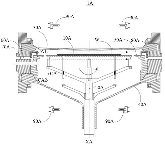
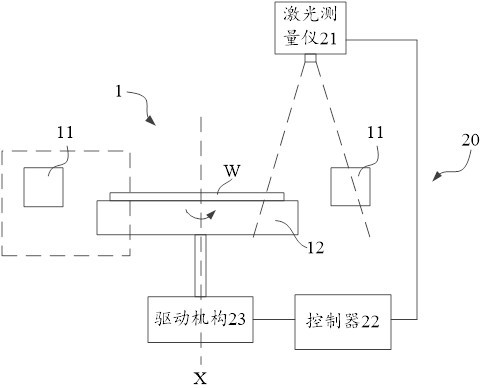
[0033] see figure 2 , which shows a system 20 for automatically adjusting the position of the susceptor 12 relative to the preheating ring 11 in the epitaxial furnace 1 provided by an embodiment of the present invention, wherein, for the purpose of clarity figure 2 Only the preheating ring 11 and the base 12 of the epitaxial furnace 1, the rotation axis X of the base 12 and the silicon wafer W carried on the base 12 are shown in the figure, other components of the epitaxial furnace 1 can be referred to figure 1 to understand, such as figure 2 The system 20 shown may include: a laser measuring instrument 21, a controller 22 and a drive mechanism 23; wherein,
[0034] The laser measuring instrument 21 is configured to measure the measured relative position information betwe...
PUM
 Abstract
Description
Claims
Application Information
 - R&D
- Intellectual Property
- Life Sciences
- Materials
- Tech Scout
- Unparalleled Data Quality
- Higher Quality Content
- 60% Fewer Hallucinations
Browse by: Latest US Patents, China's latest patents, Technical Efficacy Thesaurus, Application Domain, Technology Topic, Popular Technical Reports.
© 2025 PatSnap. All rights reserved.Legal|Privacy policy|Modern Slavery Act Transparency Statement|Sitemap|About US| Contact US: help@patsnap.com