Embroidery machine head suitable for high-speed embroidery
An embroidery machine and embroidery technology, applied to the mechanism of embroidery machines, embroidery machines, textiles and papermaking, etc., can solve the problems of complex control frame, unsatisfactory improvement effect, lack of structural versatility, etc., and achieve good operation stability, Reduce labor maintenance costs, flexible installation space selection effect
- Summary
- Abstract
- Description
- Claims
- Application Information
AI Technical Summary
Problems solved by technology
Method used
Image

Examples
Embodiment Construction
[0057] Below in conjunction with accompanying drawing, the present invention will be further described by specific embodiment:
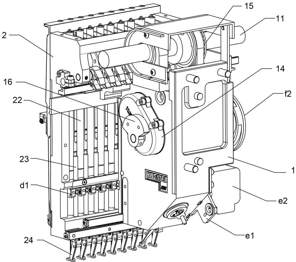
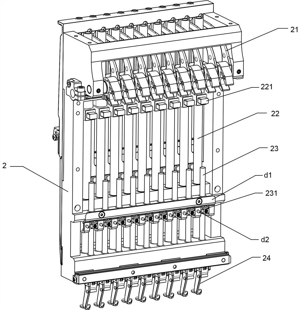
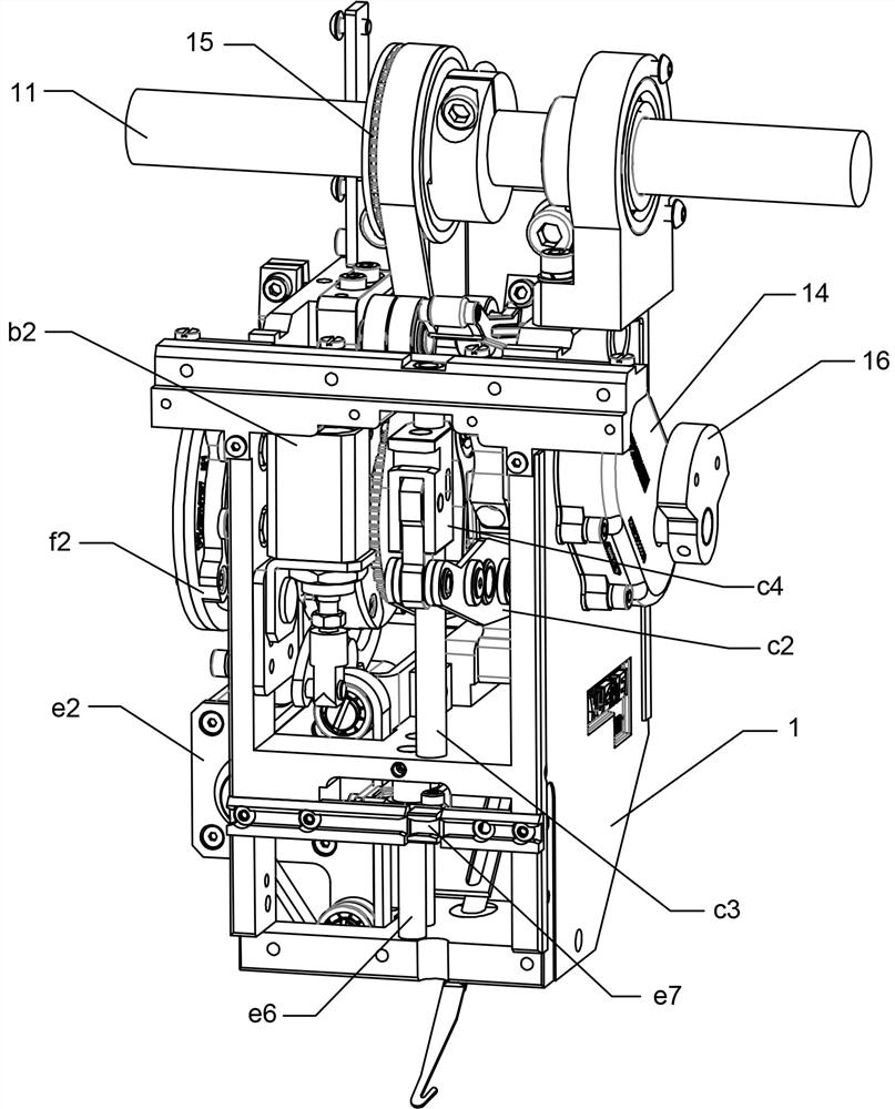
[0058] See Figure 1~Figure 5 , an embodiment of an embroidery machine head suitable for high-speed embroidery, including a casing 1 and a needle bar frame 2, the casing 1 is provided with an upper guide rail and a lower guide rail respectively with a guide rail bead group, and the needle bar frame 2 passes through The upper and lower guide rails are slidingly connected on the casing 1 and can slide horizontally. The needle bar frame 2 is provided with a thread take-up lever 21, a needle bar 22, a presser foot shaft 23 and a presser foot 24. The casing 1 is provided with a main shaft 11 for The needle bar drive mechanism for driving the needle bar 22, the presser foot drive mechanism for driving the presser foot shaft 23, the thread take-up drive mechanism for driving the thread take-up lever 21 and the thread catcher 17 for thread hooking. The casi...
PUM
 Abstract
Description
Claims
Application Information