Structure for widening bridge by additionally arranging steel bent caps on pier tops

A technology for steel cover beams and bridges, which is applied in the erection/assembly of bridges, bridges, bridge maintenance, etc., can solve the problems of insufficient strength, waste of resources, corrosion of widening beams, etc., and achieve the effect of high strength

Inactive Publication Date: 2021-03-16
谢绍良
View PDF0 Cites 0 Cited by
  • Summary
  • Abstract
  • Description
  • Claims
  • Application Information

AI Technical Summary

Problems solved by technology

This method is suitable for double-sided widening of general beam bridges and arch bridges. However, due to the limitation of its own bearing capacity, the widening span is limited, and the load acting on the cantilever should not be too large. It is usually only suitable for pedestrians and not for vehicles.
[0004] In the existing technology, there is a problem of insufficient strength when connecting the widened beams, which will cause the phenomenon that the connection strength is not enough after widening to cause vibrations to the vehicles driving on the road, and finally lead to no substantive effect and a waste of resources
[0005] In the existing technology, after the widening beam is connected, there will be gaps on the upper surface after the widening beam and the bridge body are integrated, which will cause water leakage in rainy and snowy weather and cause corrosion of the widening beam, and finally lead to the service life of the widening beam shortened result

Method used


Image

  • Structure for widening bridge by additionally arranging steel bent caps on pier tops
  • Structure for widening bridge by additionally arranging steel bent caps on pier tops
  • Structure for widening bridge by additionally arranging steel bent caps on pier tops

Examples


Embodiment Construction

[0027] The technical solutions in the embodiments of the present invention will be clearly and completely described below with reference to the accompanying drawings in the embodiments of the present invention. Obviously, the described embodiments are only a part of the embodiments of the present invention, but not all of the embodiments. Based on the embodiments of the present invention, all other embodiments obtained by those of ordinary skill in the art without creative efforts shall fall within the protection scope of the present invention.

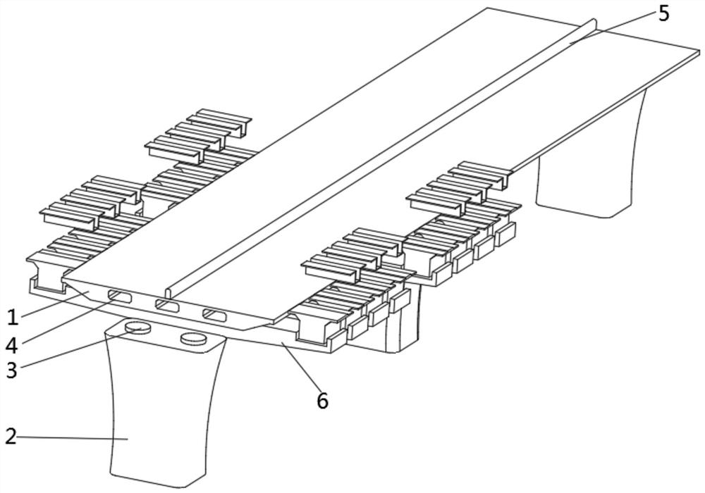
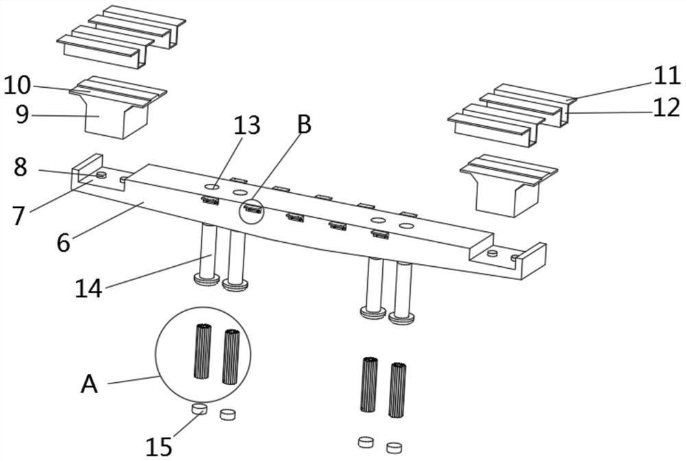
[0028] see Figures 1 to 6 , In the embodiment of the present invention, a structure for widening a bridge by adding a steel cover beam to the top of a pier includes a bridge body 1, a second screw hole 20 is opened on the lower end surface of the bridge body 1, and a widening beam 6 is arranged under the bridge body 1. The widening beam 6 is provided with a plurality of, the left and right sides of the upper end surface of the wideni...


PUM


Abstract

The invention discloses a structure for widening bridge by additionally arranging steel bent caps on pier tops. The structure comprises a bridge body, a second screw hole is formed in the lower end face of the bridge body, a broadening beam is arranged below the bridge body, side opening grooves are formed in the left side and the right side of the upper end face of the broadening beam, second buffer seats are fixedly connected with the upper end faces of the side opening grooves, a connecting beam is arranged above the second buffer seats, a communicating block is arranged above the connecting beam, an upper opening groove is formed in the upper end face of the communicating block, first screw holes are formed in the upper end face of the broadening beam, a main bolt is arranged below each first screw hole, a reinforcing steel bar is arranged below each main bolt, and plugging cement paste is arranged below each reinforcing steel bar. By arranging the widening beam, the first screw holes, the second screw holes, the reinforcing steel bars, the main bolts and the plugging cement paste, the action that the widening beam is connected with the lower end face of the bridge body and then the reinforcing steel bars are inserted into the first screw holes to be plugged through the plugging cement paste can be completed, and the effect of reinforcing connection and fastening of the widening beam is achieved.

Description

technical field [0001] The invention relates to the technical field of bridge engineering, in particular to a structure in which a steel cover beam is added to a pier top to widen a bridge. Background technique [0002] At present, the common practices in the field of bridge widening are as follows: [0003] Increase the reinforced concrete cantilever beam: remove the old bridge railings and sidewalk facilities, and increase or increase the cantilever beam to achieve the purpose of widening the bridge. This method is suitable for bilateral widening of general girder bridges and arch bridges, but limited by its own bearing capacity, the widening span is limited, and the load acting on the cantilever should not be too large, usually only suitable for pedestrians and not vehicles. [0004] The existing technology has the problem of insufficient strength when connecting the widening beams, which may cause the phenomenon that the connecting strength is insufficient after widenin...

Claims


Application Information

Patent Timeline
IPC IPC(8): E01D22/00
CPCE01D22/00
Inventor 谢绍良
Owner 谢绍良
Why Eureka
Try Eureka