
System and method for monitoring flow of regulating valve through sound waves

A technology for regulating valves and flow, applied in the direction of measuring flow/mass flow, measuring devices, liquid/fluid solid measurement, etc., to achieve low-cost online monitoring and realize the effect of price

Pending Publication Date: 2021-03-16
HUANENG CLEAN ENERGY RES INST
View PDF8 Cites 2 Cited by
  • Summary
  • Abstract
  • Description
  • Claims
  • Application Information

AI Technical Summary

Problems solved by technology

[0005] The purpose of the present invention is to provide a system and method for controlling the flow rate of a control valve with acoustic waves, so as to solve the technical problems brought by the flow meter to measure the flow rate in the prior art.

Method used


Image

  • System and method for monitoring flow of regulating valve through sound waves
  • System and method for monitoring flow of regulating valve through sound waves
  • System and method for monitoring flow of regulating valve through sound waves

Examples


Embodiment 1

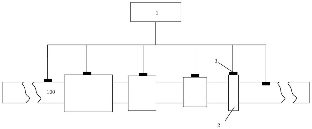
[0038] see figure 1 As shown, the present invention provides a system for regulating valve acoustic wave monitoring flow, comprising:

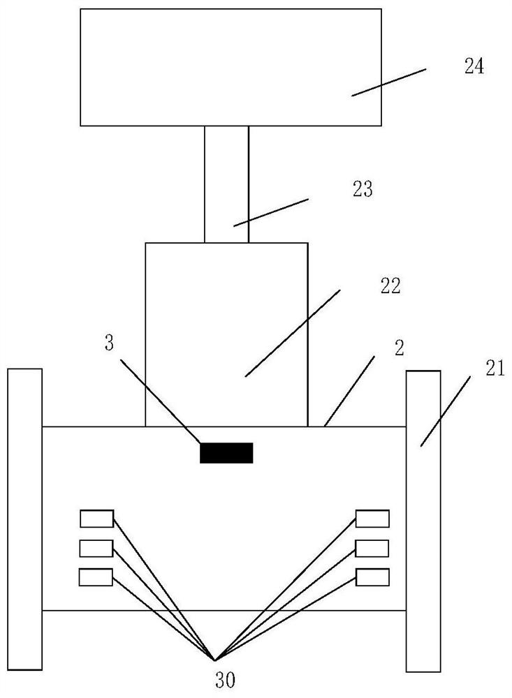
[0039] Regulating valve 2; the regulating valve is installed in the fluid pipeline 100 at intervals;

[0040] Acoustic wave sensor 3, at least one acoustic wave sensor is installed at each control valve; The sound wave sensor is arranged on the inside or outside of the control valve close to the spool; Each sound wave sensor has an ID code, and the ID code is related to the geographic location of the sound wave sensor. Geographical information coding correspondence of the location; when the acoustic wave sensor transmits the collected acoustic wave signal, geographic information coding information and model information of the corresponding regulating valve are added at the same time.

[0041] The signal transmission device is used to receive the acoustic wave signal collected by the acoustic wave sensor and send it to the acoustic wave data a...

Embodiment 2

[0048] The present invention also provides a method for monitoring the flow rate of a regulating valve by acoustic waves, which is used for monitoring the flow rate of a regulating valve, which specifically includes:

[0049] S11: Install the regulating valve and its acoustic sensor on the flow calibration experiment platform;

[0050]S12: Debug the regulating valve and its various sensors and the data acquisition system of the flow calibration experiment platform, so as to achieve the acquisition of the acoustic signal of the qualified acoustic sensor that removes noise interference and meet the calibration requirements;

[0051] S13: Debug the pressure sensor before and after the regulating valve, and the flow sensor of the calibration experiment platform to meet the calibration requirements;

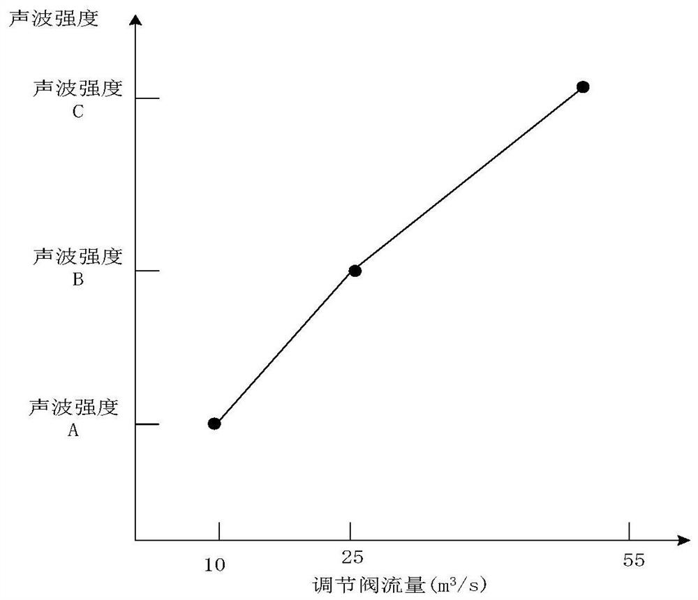
[0052] S14: Under different pre-valve pressures and different control valve flow conditions, monitor the sound wave signal collected by the sound wave sensor of the control valve; the...


PUM


Abstract

The invention discloses a system and method for monitoring flow of a regulating valve through sound waves. The system comprises the regulating valve which is installed in a fluid pipeline and comprises an actuating mechanism and a valve body part, a sound wave sensor which is mounted at the corresponding regulating valve position and used for collecting sound wave signals at the corresponding regulating valve position and transmitting the sound wave signals to a signal transmission device, the signal transmission device which is used for receiving sound wave signals collected by the sound wavesensor and sending the sound wave signals to a sound wave data analysis platform, and the sound wave data analysis platform which is used for monitoring the flow of the regulating valve by receivingthe sound wave signals uploaded by the signal transmission device. According to the system and the method, real-time monitoring of the flow of the regulating valve is realized through the relatively cheap sound wave sensor, and resistance and fault points are not brought to the fluid pipeline. The problems that conventional flow measuring equipment is expensive, and additional resistance is brought to a fluid system are solved.

Description

technical field [0001] The invention relates to the technical field of regulating valve monitoring, in particular to a system and method for acoustically monitoring flow of a regulating valve. Background technique [0002] Flow measurement is an important part of measurement science and technology. It has been widely used in various fields such as industrial and agricultural production, environmental protection, scientific research, foreign trade, people's life, etc. Accurate and fast flow measurement is very important for ensuring product quality, improving economic benefits, It plays an important role in saving energy and promoting the development of science and technology. In the era of increasingly prominent energy crisis, the status and role of flow measurement in the national economy are becoming more and more important. Flow measurement, as one of the key technologies in industrial processes, has been widely concerned and deeply researched. Common flow meters includ...

Claims


Application Information

Patent Timeline
Patent Type & Authority Applications(China)
IPC IPC(8): F16K37/00G01F1/66
CPCF16K37/0091G01F1/66
Inventor 李卫东王保民杨豫森
Owner HUANENG CLEAN ENERGY RES INST
Learn More