
Energy-saving gas windproof device

A windproof device and energy-saving technology, which is applied in household heating, lighting and heating equipment, household heating, etc., can solve problems such as poor adhesion of the bottom of the gas stove, damage to the gas stove, and blackening of the inner wall of the device. Achieve the effect of achieving fixed matching effect, strengthening the limit fixing effect, and improving the practical effect

Pending Publication Date: 2021-03-16
嘉禾县大强铸造有限公司
View PDF0 Cites 0 Cited by
  • Summary
  • Abstract
  • Description
  • Claims
  • Application Information

AI Technical Summary

Problems solved by technology

[0004] 1. The existing energy-saving gas windproof device is not strong enough to adhere to the bottom of the gas stove, and it is easy to cause the base to overheat and cause damage to the gas stove when the device is in use. Therefore, we propose an energy-saving gas windproof device to solve the current problem. some problems;
[0005] 2. The existing energy-saving gas windproof device often has the possibility of inevitable oxidation of the inner wall of the device caused by high temperature when the gas is used, which may easily lead to blackening of the inner wall of the device. For this reason, we propose an energy-saving gas windproof device to solve the problem. existing problems;
[0006] 3. Most of the existing energy-saving gas windproof devices do not have the function of adapting to the gas stove. Often, the device will loosen during use, resulting in the situation that the kitchen utensils on the device cannot be heated evenly. For this reason, we propose a An energy-saving gas windproof device to solve the existing problems

Method used

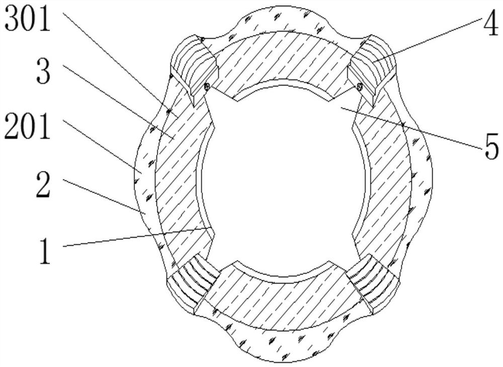
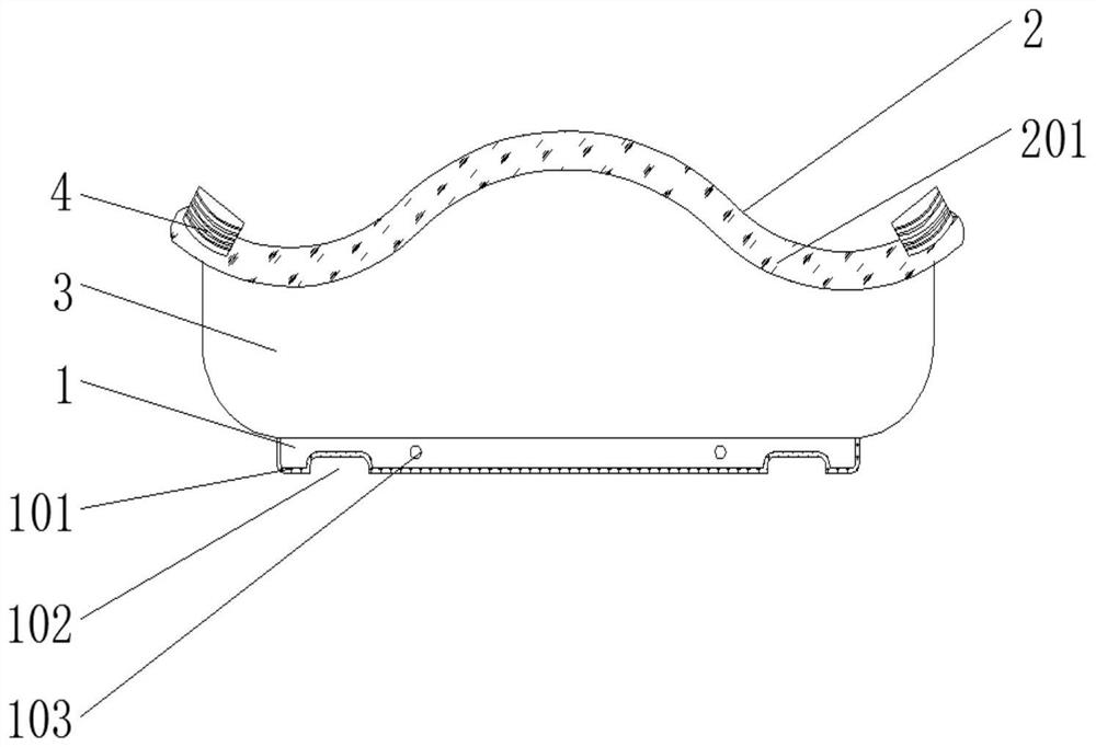
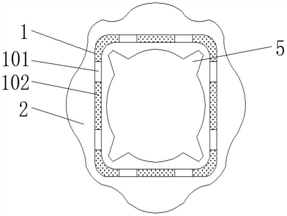

Image

  • Energy-saving gas windproof device
  • Energy-saving gas windproof device
  • Energy-saving gas windproof device

Examples


Embodiment Construction

[0024] The following will clearly and completely describe the technical solutions in the embodiments of the present invention with reference to the accompanying drawings in the embodiments of the present invention. Obviously, the described embodiments are only some, not all, embodiments of the present invention. Based on the embodiments of the present invention, all other embodiments obtained by persons of ordinary skill in the art without making creative efforts belong to the protection scope of the present invention.

[0025] In the description of the present invention, it should be noted that the terms "upper", "lower", "inner", "outer", "front end", "rear end", "both ends", "one end", "another end" The orientation or positional relationship indicated by etc. is based on the orientation or positional relationship shown in the drawings, and is only for the convenience of describing the present invention and simplifying the description, rather than indicating or implying that ...


PUM


Abstract

The invention discloses an energy-saving gas windproof device which comprises a base, arc-shaped attaching bases, a windshield metal block, limiting slots, metal blocks and a metal cushion block, wherein a soft adhesive tape is mounted on the lower surface of the base in an adhering mode, a windshield is mounted on the upper surface of the base in a welded mode, and a titanium alloy layer is welded to the outer surface of the windshield; limiting slots are evenly distributed in the bottom side of the wind shield, arc-shaped attaching bases are evenly distributed on the outer surface of the wind shield, and metal blocks are welded and mounted between the arc-shaped attaching bases and the wind shield at equal intervals. The titanium alloy layer is welded to the outer surface of the wind shield and has the characteristics of high temperature resistance and oxidation resistance, so that the problem that aesthetic property of the device is affected as inner wall blackening caused by oxidative reaction on the inner wall of the device while an inevitable burning condition of the inner wall of the device is caused by flames during use of the device is effectively prevented, and the practicability of the device is further improved.

Description

technical field [0001] The invention relates to the technical field of gas wind protection, in particular to an energy-saving gas wind protection device. Background technique [0002] Natural gas and coal gas resources, as a kind of pollution-free energy, have always been the first-choice resources for cooking heat in existing domestic kitchens, but the utilization rate of gas in existing domestic gas stoves is only 60% to 70%, and some of the heat is too late It is absorbed by the pot body and lost into the air, causing a lot of waste. The external wind force also has an impact on the burning flame. Windproof treatment, for this reason, energy-saving gas windproof device came into being. [0003] The defective that existing energy-saving gas windproof device exists is: [0004] 1. The existing energy-saving gas windproof device is not strong enough to adhere to the bottom of the gas stove, and it is easy to cause the base to overheat and damage the gas stove when the devi...

Claims


Application Information

Patent Timeline
Patent Type & Authority Applications(China)
IPC IPC(8): F24C15/28F24C15/34F24C15/10
CPCF24C15/28F24C15/34F24C15/107
Inventor 彭段越
Owner 嘉禾县大强铸造有限公司
Learn More