2D online detection method for high-precision cutter wear

A technology for tool wear and detection methods, applied in measuring devices, instruments, etc., can solve the problems of low detection accuracy, difficult detection steps, disassembly of tools or workpieces, etc., to achieve simple principles and operation steps, high-precision wear measurement, The effect of improving processing efficiency

Active Publication Date: 2021-03-16
DALIAN UNIV OF TECH
View PDF14 Cites 2 Cited by
  • Summary
  • Abstract
  • Description
  • Claims
  • Application Information

AI Technical Summary

Problems solved by technology

[0005] Although the above tool detection method can reflect the wear of the tool to a certain extent, when the radius of the blunt circle of the cutting edge is in the same order of magnitude as the radius of the CMM probe, the probe radius has a significant impact on the measurement results, and the detection accuracy Not high; there are still some problems such as difficult to realize the detection steps, slow detection speed, need to disassemble the tool or workpiece during measurement, and cannot measure online

Method used


Image

  • 2D online detection method for high-precision cutter wear
  • 2D online detection method for high-precision cutter wear
  • 2D online detection method for high-precision cutter wear

Examples


Embodiment 1

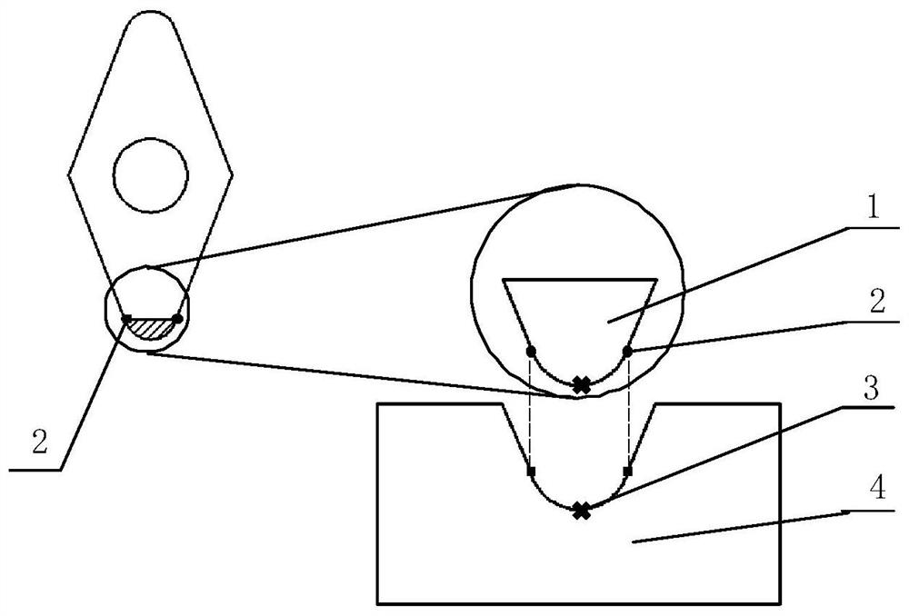
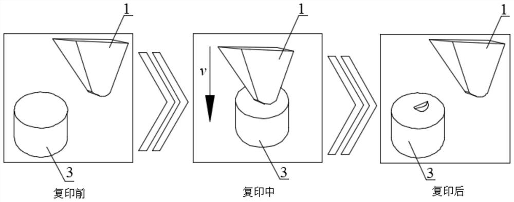
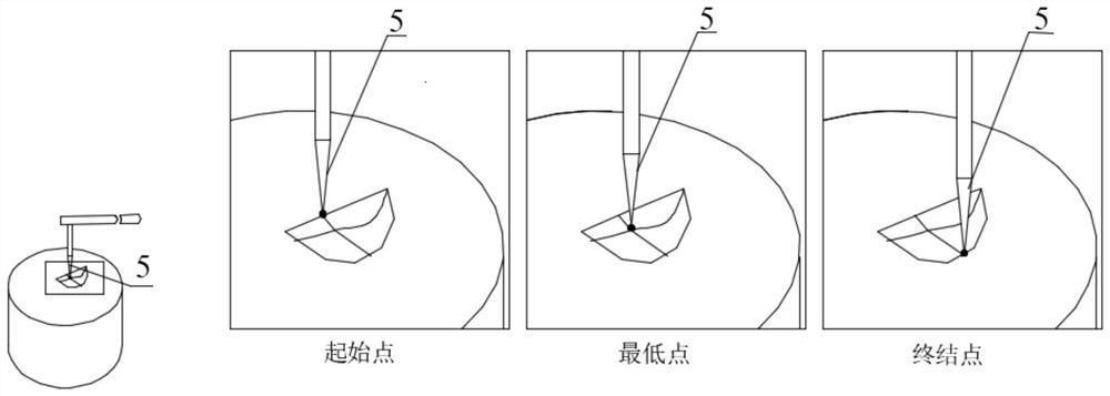
[0045] Such as Figure 1-5 As shown, the steps of the 2D detection process of tool 1 wear under the condition that the radius of the blunt circle of the tool 1 is smaller than the radius of the probe 5 of the contact profile measuring device using the method of the present invention are as follows:

[0046] A. Take two pieces of soft metal 4, grind and polish their upper and lower surfaces by mechanical polishing, after reaching a surface roughness of less than 100 nanometers and a flatness of less than several microns, clean them with deionized water, and dry them for later use.

[0047] B. Trial machining a groove with a length of 10mm with unworn tool 1, and predict the radius R of the blunt circle of tool 1 according to the surface morphology of the groove t Size, by comparison, tool 1 blunt circle radius R t Less than the radius R of the contact profilometer probe 5 p size, it is necessary to remove the influence of the radius of the probe 5 of the measuring device to ach...

Embodiment 2

[0062] Such as Figure 1-5 As shown, using the method of the present invention, the tool 1 wear 2D detection process steps under the condition that the radius of the blunt circle of the tool 1 is much larger than the radius of the probe 5 of the contact profile measuring device are as follows:

[0063] A. Take two pieces of soft metal 4, grind and polish their upper and lower surfaces by mechanical polishing, after reaching a surface roughness of less than 100 nanometers and a flatness of less than several microns, clean them with deionized water, and dry them for later use.

[0064] B. Trial machining a groove with a length of 10mm with the unworn tool 1, and predict the radius R of the blunt circle of the cutting edge according to the surface morphology of the groove t , and then with the radius size R of the probe 5 used by the contact profilometer p Comparing that, we get R t much larger than R p . Therefore, direct measurement of the dents left on the soft metal 4 bef...


PUM

PropertyMeasurementUnit
Hardnessaaaaaaaaaa

Abstract

The invention discloses a 2D online detection method for high-precision tool wear. The 2D online detection method comprises the steps of pretreating a soft metal surface; pre-judging the blunt radiusof the cutting edge of the cutter; determining a measurement path; pressing soft metal into the cutter; measuring a dent profile before the cutter is worn; measuring a dent profile after the cutter isworn; and conducting tool wear analysis. According to the method, the cutter is creatively re-engraved on the soft metal to leave the mark, the size of the re-engraved blunt radius is obtained by fitting scanning point data of the dent, and the wear condition of the cutter is indirectly obtained. Whether compensation is carried out or not is determined according to the size relation between the probe radius of the contact type profile measurement equipment and the blunt radius of the cutting edge of the cutter, so that scanning point coordinate data before and after the cutter is worn can beaccurately obtained, the wear condition of the cutter can be visually known by comparing the fitted circle radius before and after the wear, and higher-precision wear measurement is realized. According to the invention, online monitoring of tool wear can be realized, and the machining efficiency can be improved.

Description

technical field [0001] The invention belongs to the field of tool wear detection, in particular to a high-precision 2D online detection method for tool wear. Background technique [0002] Ultra-precision machining is a key technology for the development of modern high-tech warfare, high-tech industry and cutting-edge technology. Diamond tools can well meet the requirements of ultra-precision cutting. Therefore, the evaluation and measurement technology of diamond tool wear is an important supporting technology for ultra-precision cutting , has great application prospects. The wear of the tool will lead to the deterioration of its cutting performance, which will reduce the machining accuracy of the workpiece to be processed, increase the surface roughness of the workpiece, and seriously cause vibration in the cutting process, affect production efficiency, and even cause safety accidents. The detection of tool wear and avoiding the use of excessively worn tools is an effectiv...

Claims


Application Information

Patent Timeline
IPC IPC(8): G01B21/20G01B21/10
CPCG01B21/10G01B21/20
Inventor 蔡引娣郭江赵勇冯健侯飞
Owner DALIAN UNIV OF TECH
Why Eureka
Try Eureka