Tunnel seepage test device
A test device and tunnel technology, which is applied in the direction of measurement device, permeability/surface area analysis, suspension and porous material analysis, etc., can solve the problems of tunnel ring dead-leg and longitudinal dead-leg, etc., so as to facilitate the test process and Phenomenon, principle scientific and reliable, simple structure effect
- Summary
- Abstract
- Description
- Claims
- Application Information
AI Technical Summary
Problems solved by technology
Method used
Image
Examples
Embodiment 1
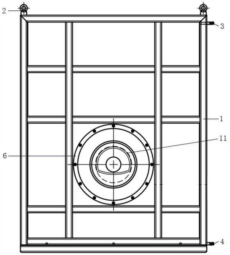
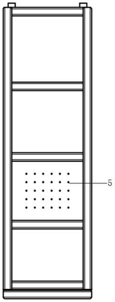
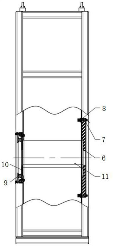
[0017] The main structure of the tunnel seepage test device involved in this embodiment includes a model box 1, a suspension ring 2, an upper water inlet 3, a lower water inlet 4, a wire hole 5, a front cover 6, a front cover gasket 7, and an O-shaped front cover. Sealing ring 8, rear cover 9, rear cover O-ring 10, tunnel model 11, circular dead-leg 12, horizontal dead-leg 13 and longitudinal dead-leg 14; the top of the model box 1 with hollow rectangular structure There are two rings 2 of circular or rectangular structure, the upper part of the model box 1 is provided with an upper water inlet 3, the lower part of the model box 1 is provided with a lower water inlet 4, and the side wall of the model box 1 is provided with several circular structures. Wire hole 5, front cover plate 6 of circular structure is provided on the front of model box 1, model box 1 and front cover plate 6 are connected by bolts, and front cover plate of circular structure is arranged between model box ...
Embodiment 2
[0019]The tunnel seepage test device involved in this embodiment simulates the process of the seepage field under the normal drainage of the tunnel as follows: lay a 5cm thick gravel layer around the side wall of the model box 1 to speed up the seepage velocity of the groundwater, and then fill the surrounding rock in layers. The material is to simulate the surrounding rock, and the filling thickness of each layer is 20cm. After each layer is filled, it is manually tamped. When the filling thickness is 60cm, the prefabricated tunnel model 11 is placed in the middle of the model box 1, and the outer wall of the tunnel model 11 is bonded. There are multi-layer woven geotextiles with permeability coefficients that meet the requirements to simulate the initial support of the tunnel. Micro-water pressure gauges and strain gauges that have undergone waterproof treatment are buried at designated positions around the tunnel model 11, and the wires of the micro-pressure gauges and strain...
Embodiment 3
[0021] The tunnel seepage test device involved in this embodiment simulates the process of the seepage field under the condition of tunnel blockage as follows: lay a 5cm thick gravel layer around the side wall of the model box 1 to speed up the seepage velocity of groundwater, and then fill it in layers similar to the surrounding rock The material is to simulate the surrounding rock, and the filling thickness of each layer is 20cm. After each layer is filled, it is manually tamped. When the filling thickness is 60cm, the prefabricated tunnel model 11 is placed in the middle of the model box 1, and the outer wall of the tunnel model 11 is bonded. There are multi-layer woven geotextiles with a permeability coefficient that meets the requirements to simulate the initial support of the tunnel. The circumferential dead-leg 12 and the longitudinal dead-leg 14 are filled with different contents of long-staple cotton, and the simulated circumferential dead-leg 12 and the longitudinal de...
PUM
 Abstract
Description
Claims
Application Information
 - R&D
- Intellectual Property
- Life Sciences
- Materials
- Tech Scout
- Unparalleled Data Quality
- Higher Quality Content
- 60% Fewer Hallucinations
Browse by: Latest US Patents, China's latest patents, Technical Efficacy Thesaurus, Application Domain, Technology Topic, Popular Technical Reports.
© 2025 PatSnap. All rights reserved.Legal|Privacy policy|Modern Slavery Act Transparency Statement|Sitemap|About US| Contact US: help@patsnap.com


