Ultrasonic detection wheel calibration system and method
A calibration system, ultrasonic technology, applied in the direction of material analysis, measuring devices, instruments, etc. using sound waves/ultrasonic waves/infrasonic waves, can solve problems such as low efficiency and time-consuming, achieve accurate calibration, improve calibration operation efficiency, and save replacement the effect of time
- Summary
- Abstract
- Description
- Claims
- Application Information
AI Technical Summary
Problems solved by technology
Method used
Image

Examples
Embodiment 1
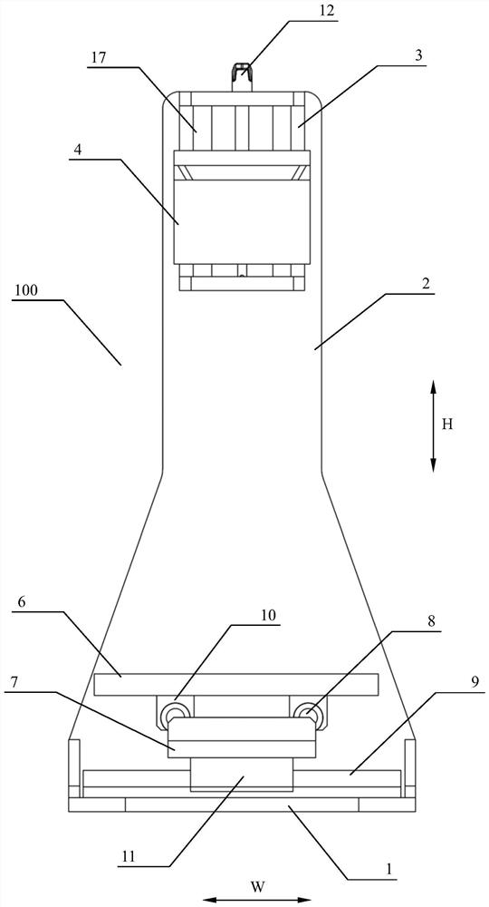
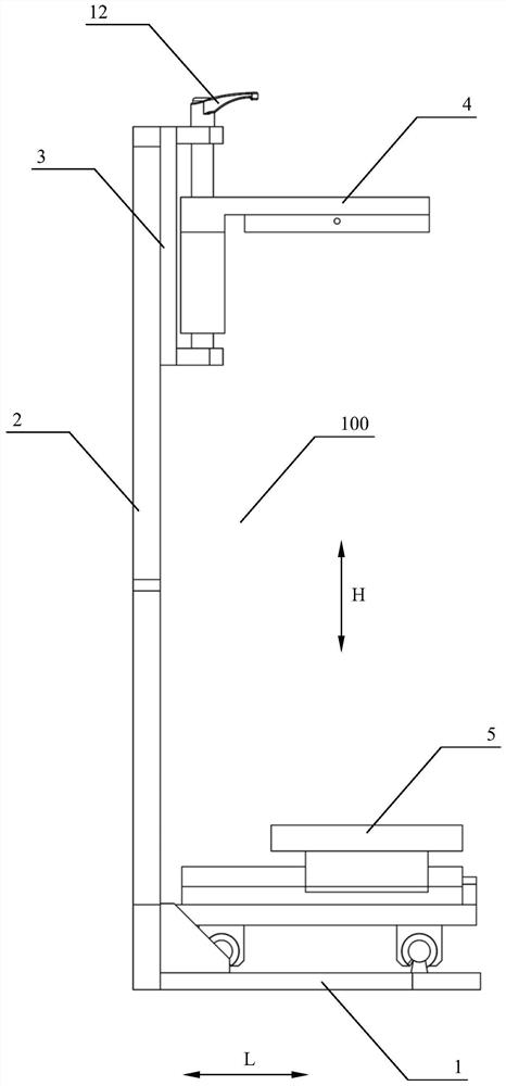
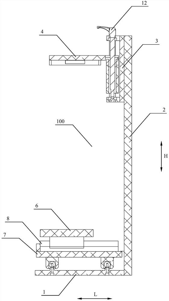
[0077] as attached figure 1 To attach Figure 4 , 7 , 8, a kind of embodiment of the ultrasonic probe wheel calibration device 100 based on the system of the present invention, the device specifically includes:
[0078] base1;
[0079] A mounting frame 2 vertically arranged on the base 1;
[0080] The lifting mechanism 3 arranged on the mounting frame 2;
[0081] It is arranged on the lifting mechanism 3 and is used to fix the detection wheel installation part 4 of the detection wheel 20. The detection wheel installation part 4 can be vertically on the lifting mechanism 3 (as attached figure 1 To attach image 3 , 7 , 8 in the direction shown by H) to move; as a typical specific embodiment of the present invention, the probe wheel 20 can be further mounted in the dovetail groove of the probe wheel installation part 4;
[0082] The bearing part 5 arranged on the base 1, relative to the bearing part 5, the probe wheel 20 can change its relative position in two directions ...
Embodiment 2
[0089] Another embodiment of the ultrasonic probe wheel calibration device 100 based on the system of the present invention, the device specifically includes:
[0090] base1;
[0091] A mounting frame 2 vertically arranged on the base 1;
[0092] The lifting mechanism 3 arranged on the mounting frame 2;
[0093] It is arranged on the lifting mechanism 3 and is used to fix the detecting wheel mounting part 4 of the detecting wheel 20. The detecting wheel mounting part 4 can move vertically on the lifting mechanism 3; as a typical embodiment of the present invention, the detecting wheel 20 Can be further mounted in the dovetail groove of the probe mounting part 4;
[0094] The bearing part 5 arranged on the base 1, relative to the bearing part 5, the probe wheel 20 can change its relative position in two directions perpendicular to each other. Vertical and vertical movement. As a typical embodiment of the present invention, the probe wheel mounting part 4 can move vertically r...
Embodiment 3
[0102] as attached Figure 9 And attached Figure 10 As shown, an embodiment of the ultrasonic probe wheel calibration system of the present invention, the system specifically includes:
[0103] The ultrasonic probe wheel calibration device 100 as described in Embodiment 1;
[0104] The liquid storage tank 13 arranged on the first longitudinal moving part 6 of the ultrasonic probe calibration device 100, the liquid storage tank 13 is filled with the probe liquid 14;
[0105] The calibration test block 16 arranged in the liquid storage tank 13 is provided with artificial damage in the calibration test block 16, which is used to test the performance of the probe wheel 20; the liquid storage tank 13 and the calibration test block 16 can be disassembled;
[0106] The sheet-shaped wheel membrane 15 arranged on the top of the calibration test block 16, the sheet-shaped wheel membrane 15 is used to simulate the amplitude attenuation generated when the ultrasonic wave passes through...
PUM
 Abstract
Description
Claims
Application Information
 - Generate Ideas
- Intellectual Property
- Life Sciences
- Materials
- Tech Scout
- Unparalleled Data Quality
- Higher Quality Content
- 60% Fewer Hallucinations
Browse by: Latest US Patents, China's latest patents, Technical Efficacy Thesaurus, Application Domain, Technology Topic, Popular Technical Reports.
© 2025 PatSnap. All rights reserved.Legal|Privacy policy|Modern Slavery Act Transparency Statement|Sitemap|About US| Contact US: help@patsnap.com