Turbine guide vane and guider throat area calculation method

A technology of turbine guide vanes and calculation methods, applied in design optimization/simulation, geometric CAD, hydropower and other directions, can solve problems such as large window height error, large throat area error, inability to solve gas film holes, etc., to improve accuracy , the effect of accurate calculation results

Active Publication Date: 2021-03-16
AECC SHENYANG ENGINE RES INST
View PDF4 Cites 6 Cited by
  • Summary
  • Abstract
  • Description
  • Claims
  • Application Information

AI Technical Summary

Problems solved by technology

This method cannot solve the above-mentioned air film hole interference and edge plate blocking problems
In addition, due to the casting difference of the blade surface or runner surface in the existing method, the measurement position is not the actual blade throat coordinate point; for the curved and twisted blade, the error of the window height calculated by this method is relatively large
At the same time, the existing methods all use the Cartesian coordinate system to measure and calculate the width of several throat area sections parallel to the engine axis, and the width sections are unevenly distributed in the radial direction of the measurement channel.
And it does not take into account the influence of the arc surface of the edge plate and the fillet between the edge plate and the blade on the throat area
Therefore, the throat area measured by the existing method has a large error

Method used


Image

  • Turbine guide vane and guider throat area calculation method
  • Turbine guide vane and guider throat area calculation method
  • Turbine guide vane and guider throat area calculation method

Examples


Embodiment Construction

[0042] In order to make the purpose, technical solution and advantages of the application more clear, the technical solution in the embodiment of the application will be described in more detail below in conjunction with the drawings in the embodiment of the application. In the drawings, the same or similar reference numerals denote the same or similar elements or elements having the same or similar functions throughout. The described embodiments are some, but not all, embodiments of the application. The embodiments described below by referring to the figures are exemplary, and are intended to explain the present application, and should not be construed as limiting the present application. Based on the embodiments in this application, all other embodiments obtained by persons of ordinary skill in the art without creative efforts fall within the protection scope of this application. Embodiments of the present application will be described in detail below in conjunction with th...


PUM


Abstract

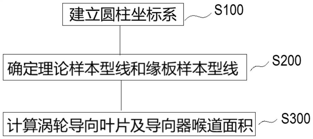
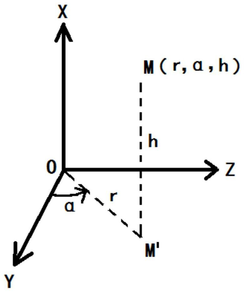
The invention belongs to the field of aero-engine turbine guide blades, and particularly relates to a turbine guide blade and a guider throat area calculation method. The method comprises: establishing a cylindrical coordinate system; determining a theoretical width sample molded line and an edge plate sample molded line; and calculating the throat areas of the turbine guide vane and the guider. According to the turbine guide blade and guider throat area calculation method, the influence of concave structures such as air film holes and tail clearances on throat area measurement is avoided; theproblem of measurement difficulty caused by geometric space limitation of the runner surface of the margin plate is solved; the problem that width molded lines are intercepted from sections parallelto the axis of the engine under different Z values, so that the distribution of the width sections in a measurement channel is not uniform in the radial direction, and then large errors are caused issolved. And the influence of the arc surface of the margin plate and the fillet between the margin plate and the blade on the throat area is considered, so that the calculation accuracy is improved.

Description

technical field [0001] The application belongs to the field of turbine guide vanes of aero-engines, and in particular relates to a method for calculating the throat area of ​​turbine guide vanes and guides. Background technique [0002] The size of the throat area of ​​the turbine guide directly affects the temperature before and after the turbine stage, the air flow field, the flow rate, thrust, speed, fuel consumption rate of the engine, etc., and also has a great impact on the stable operation of the engine and the matching performance of the compressor and the turbine. It is an important parameter to determine the overall performance of the engine. [0003] For turbine guide vanes, especially high-pressure turbine guide vanes, there are often hundreds of air film holes on the edge plate and blade body, and tail splits are often arranged on the trailing edge of the blade body. Due to the processing deviation of actual blades, it is difficult to ensure that under the same...

Claims


Application Information

Patent Timeline
Patent Type & Authority Applications(China)
IPC IPC(8): G06F30/17G06F30/20
CPCG06F30/20G06F30/17Y02E10/20
Inventor 屈云凤张志强曾令玉
Owner AECC SHENYANG ENGINE RES INST
Why Eureka
Try Eureka