An intelligent interpretation method of rock mass structural plane based on point cloud and GPU technology

A structural surface and rock mass technology, applied in the field of intelligent interpretation of rock mass structural surfaces based on point cloud and GPU technology, can solve problems such as point cloud extraction of structural surfaces, distortion of surface details, failure to meet efficiency requirements, etc., to achieve The effect of retaining authenticity and integrity, improving extraction accuracy, and accelerating calculation speed

A structural surface and rock mass technology, applied in the field of intelligent interpretation of rock mass structural surfaces based on point cloud and GPU technology, can solve problems such as point cloud extraction of structural surfaces, distortion of surface details, failure to meet efficiency requirements, etc., to achieve The effect of retaining authenticity and integrity, improving extraction accuracy, and accelerating calculation speed

CN112508766BActive Publication Date: 2022-04-26HUBEI UNIV OF TECH +2

Image

  • An intelligent interpretation method of rock mass structural plane based on point cloud and GPU technology
  • An intelligent interpretation method of rock mass structural plane based on point cloud and GPU technology
  • An intelligent interpretation method of rock mass structural plane based on point cloud and GPU technology

Examples


specific Embodiment approach

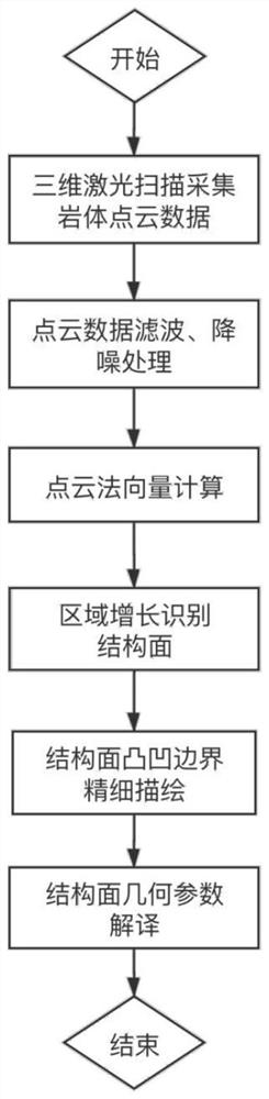
[0066] see figure 1 , shown as the concrete flowchart of the inventive method, a kind of embodiment of the present invention will be provided below in conjunction with flowchart, and the steps are as follows:

[0067] 1. Use 3D scanning technology to collect rock mass point cloud data.

[0068] This step is prior art. When collecting 3D laser point cloud data of rock masses in the field, the site range for the scanner should be designed according to the outcrop range, spatial conditions and accuracy requirements of the deposit; a tripod should be set up on a flat and hard ground within the site range to ensure scanning The stability of the instrument when working.

[0069] 2. Splice and denoise the point cloud data.

[0070] This step is a preprocessing step of the point cloud data, and also belongs to the conventional technology in the field of three-dimensional scanning technology. The purpose of preprocessing is to improve the accuracy of point cloud data and obtain poi...

Embodiment

[0158] In conventional methods, the calculation of normal vectors of point cloud points is the most time-consuming link. In the face of massive point clouds, the calculation speed of normal vectors fundamentally determines the efficiency of structural surface extraction. This embodiment adopts the method of the present invention (combination method of GPU and linear regression, abbreviated as GPU+linear regression) and conventional method (combination of CPU and PCA, abbreviated as CPU+PCA), respectively for two groups of point cloud data sets A and B Carry out the normal vector calculation, and compare the calculation time consumption, the results are shown in Table 1. It can be seen from the table that the method of the present invention is fully applicable to the normal vector calculation of massive point clouds, and significantly reduces time consumption.

[0159] Table 1 Time-consuming comparison of normal vector calculation

[0160]


PUM


Abstract

The invention discloses an intelligent interpretation method of rock mass structural plane based on point cloud and GPU technology, and the collected rock mass laser point cloud data is processed as follows: the first step is to calculate the point cloud based on GPU parallel computing and linear regression method The normal vector of each point in the data; the second step, using the improved region growing method to identify the structural surface feature point set; the third step, using the improved convex hull scanning method to extract the structural surface boundary from the final structural surface feature point set; Four steps, automatically interpret the trace length, occurrence and spacing of the structural surface based on the contour point calculation. The method of the present invention can realize the extremely fast calculation of massive point cloud data, break through the efficiency bottleneck of identifying structural planes based on point clouds in the past, accurately, quickly and efficiently obtain rock mass structural plane information, and at the same time can perform high-precision delineation of structural plane boundaries, and then Calculate the exact trace length of the structural plane.

Description

technical field [0001] The invention belongs to the technical field of rock mass structural plane extraction, in particular to an intelligent interpretation method for rock mass structural planes based on point cloud and GPU technology. Background technique [0002] Due to the developed structural planes inside the rock mass, the rock mass shows a certain structure, and also directly affects the mechanical properties of the rock mass. How to efficiently and accurately obtain the geometric information of rock mass discontinuities has become a hot and difficult problem in rock mass engineering. In actual engineering, due to the advantages of convenient measurement means and accurate measurement results, the manual on-site contact measurement method is widely used in structural surface measurement. However, this method has some disadvantages, such as low contact measurement efficiency, potential safety hazards and incomplete measurement results. [0003] Three-dimensional las...

Claims


Application Information

Patent Timeline
26 Apr 2022
Publication
CN112508766B
IPC
G06T1/20; G01B11/25
CPC
G06T1/20; G01B11/254
Inventors
陈娜; 夏金梧