Supercharge Your Innovation With Domain-Expert AI Agents!

Milling method

A milling and spindle technology, applied to milling machine equipment, milling machine equipment details, program control, etc., can solve problems such as offset and optical inhomogeneity

Active Publication Date: 2021-03-16
ECRON LLC
View PDF7 Cites 1 Cited by
  • Summary
  • Abstract
  • Description
  • Claims
  • Application Information

AI Technical Summary

Problems solved by technology

However, sometimes an offset occurs, which can result in an optically non-uniform appearance (wider streaks) on the surface

Method used


Image

  • Milling method
  • Milling method
  • Milling method

Examples


Embodiment Construction

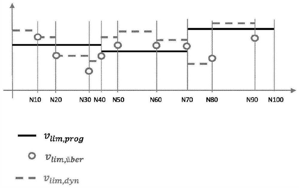
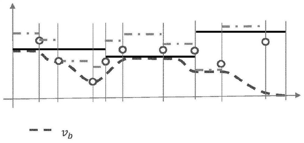
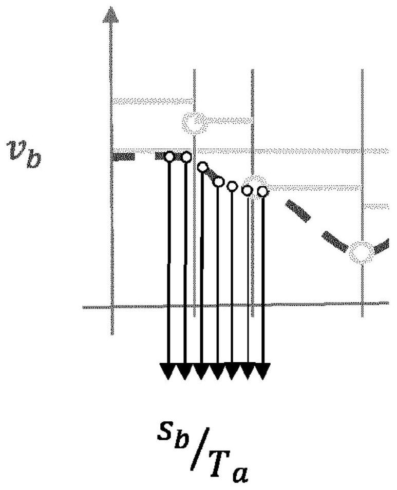
[0030] NC (Numerical Control) programs describe milling paths as a series of simple geometric elements. A support point or path support point is the corresponding boundary between two subsequence geometric elements. These coordinates are obtained as NC blocks from the NC program for each line. The path parameter (also called path length integral) describes exactly one point on the path described in the part program, which can lie exactly between the support points of the NC block.

[0031] In the following, a synchronization point is to be understood as any point of a path (= path parameter) that is applied simultaneously:

[0032] nSpdl=nprog (spindle speed is the value specified in the program)

[0033] vb=vprog (the feed rate is the value specified in the program)

[0034]

[0035] aSpdl=0 (spindle speed is constant)

[0036] ab=0 (spindle is not accelerated in x, y, z directions)

[0037] A trigger point is a starting point (in time and / or path parameters) for plan...


PUM


Abstract

The invention relates to a method for machining a workpiece by means of a milling tool arranged on a rotatable spindle, the spindle being moved relative to the workpiece or the workpiece being moved relative to the spindle along a machining path and, at the same time, the spindle rotating about a spindle axis. In said method, an improvement in the surface quality is achieved by controlling the rotational speed and / or the phase position of the rotation of the spindle along the machining path, the machining path comprising linear parallel tracks and the phase position of the spindle along the machining path being substantially the same on adjacent tracks, the phase position being controlled by varying the rotational speed of the spindle and / or the advancing speed of the spindle relative to the workpiece along the machining path.

Description

technical field [0001] The invention relates to a method for machining a workpiece with a milling tool arranged on a rotatable spindle, wherein the spindle moves relative to the workpiece along a machining path or the workpiece moves along a machining path relative to the spindle and the spindle surrounds the spindle Axis rotation, wherein the phase position and / or rotational speed of the rotation of the main shaft along the machining path are controlled, and the invention relates to an apparatus and a computer program for performing the method, as well as for encoding the computer program data structure. Background technique [0002] In modern machine tools, numerical control is used to control the positioning and movement of the tool relative to the workpiece. In order to machine a workpiece according to specifications, it is necessary to move the tool relative to the workpiece on a predetermined path. Therefore, this is also called path control. Define the required pat...

Claims


Application Information

Patent Timeline
Patent Type & Authority Applications(China)
IPC IPC(8): G05B19/4093
CPCG05B19/40937G05B2219/34175B23C3/00Y02P90/02G05B2219/49077
Inventor J·梅耶
Owner ECRON LLC
Features
  • R&D
  • Intellectual Property
  • Life Sciences
  • Materials
  • Tech Scout
  • Unparalleled Data Quality
  • Higher Quality Content
  • 60% Fewer Hallucinations
Learn More