Particle separation structure and smoke dust treatment device

A particle separation and treatment device technology, applied in the direction of dispersed particle separation, combination device, separation method, etc., can solve the problems of low use value, secondary separation treatment, incomplete smoke and dust treatment, etc.

Inactive Publication Date: 2021-03-19
金保财
View PDF0 Cites 1 Cited by
  • Summary
  • Abstract
  • Description
  • Claims
  • Application Information

AI Technical Summary

Problems solved by technology

[0004] Based on the existing soot treatment, only the flue gas and particles are separated, and then the flue gas is treated, but the separated particles cannot be subjected to secondary separation treatment, resulting in incomplete treatment of soot and low use value. The invention proposes a particle separation structure and a soot treatment device

Method used


Image

  • Particle separation structure and smoke dust treatment device
  • Particle separation structure and smoke dust treatment device
  • Particle separation structure and smoke dust treatment device

Examples


Embodiment 1

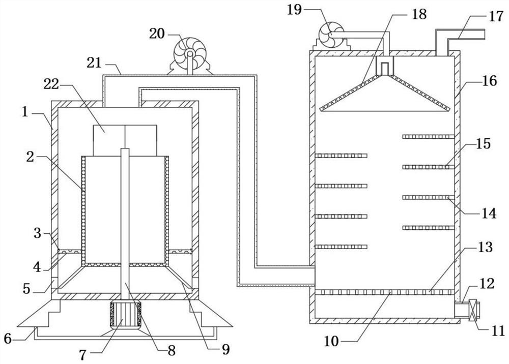
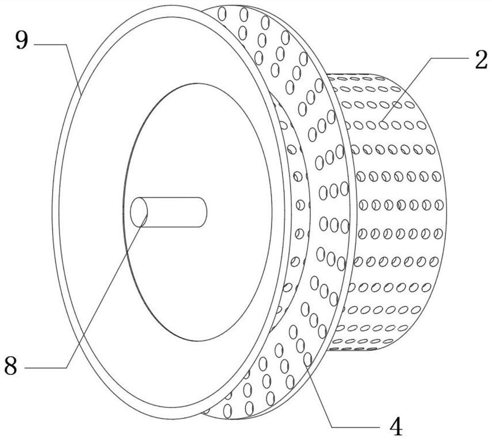
[0025] refer to Figure 1-3 , a particle separation structure and smoke treatment device, including a treatment box 1 and a spray tower 16, the bottom outer wall of the treatment box 1 is fixedly connected with a base 6, and the inner wall of the base 6 is fixedly connected with a motor 7, and the output shaft of the motor 7 passes through The shaft coupling is fixedly connected with the rotating shaft 8, and the outer wall of the rotating shaft 8 is fixedly connected with the screen cylinder 2, the outer wall of the screen cylinder 2 is fixedly connected with the sieve plate 4, and the inner wall of the processing box 1 is fixedly connected with the ring chute 3, the sieve plate 4 Slidingly connected to the inner wall of the circular chute 3, the processing box 1 is provided with a door 22 that can be opened and closed, and the sieve plate 4 can be replaced or cleaned by opening the door 22, and the bottom outer wall of the sieve drum 2 is fixedly connected with a drainage pla...

Embodiment 2

[0034] refer to Figure 1-4 , a particle separation structure and smoke treatment device, including a treatment box 1 and a spray tower 16, the bottom outer wall of the treatment box 1 is fixedly connected with a base 6, and the inner wall of the base 6 is fixedly connected with a motor 7, and the output shaft of the motor 7 passes through The shaft coupling is fixedly connected with the rotating shaft 8, and the outer wall of the rotating shaft 8 is fixedly connected with the screen cylinder 2, the outer wall of the screen cylinder 2 is fixedly connected with the sieve plate 4, and the inner wall of the processing box 1 is fixedly connected with the ring chute 3, the sieve plate 4 Slidingly connected to the inner wall of the circular chute 3, the outer wall of the bottom of the screen cylinder 2 is fixedly connected with a drainage plate 9, and the drainage plate 9 is a ring structure, and the outer wall of the treatment box 1 near the bottom of the drainage plate 9 is provide...


PUM


Abstract

The invention belongs to the technical field of smoke dust treatment, particularly relates to a particle separation structure and a smoke dust treatment device, and aims to solve the problems of incomplete smoke dust treatment and relatively low use value due to the fact that only smoke and particles are separated and then smoke is treated during existing smoke dust treatment, but separated particles cannot be subjected to secondary separation treatment. According to the scheme, the device comprises a treatment box and a spray tower, a base is fixedly connected to the outer wall of the bottomof the treatment box, and a motor is fixedly connected to the inner wall of the base. By arranging the motor, a screen drum, a screen plate and a drainage plate, when smoke and particles of smoke areseparated, the motor is started and drives the screen drum to rotate at a high speed through the rotating shaft, so that the particles in the smoke are discharged from the screen holes, the smoke rises, the thrown-out particles fall on the screen plate, and the screen plate rotating at a high speed conducts secondary separation on the particles; and the separated particles are directly guided to an annular discharge hole through the drainage plate to be discharged, so that the use value of the smoke dust treatment device is improved.

Description

technical field [0001] The present invention relates to the technical field of soot treatment, in particular to a particle separation structure and a soot treatment device. Background technique [0002] The solid particles suspended in the gas formed during the thermal process of oxidation, sublimation, evaporation and condensation are called soot. For example, converter flue gas contains a large amount of extremely fine dust. Areas with severe desertification will be blown by strong winds to create a large smoke storm; smoke and dust are solid particles emitted during coal burning and industrial production; its main components are silica, alumina, iron oxide, and calcium oxide and unburned charcoal particles, etc. There are many kinds of air pollutants, which can be divided into two categories according to the form, namely, particulate pollutants and harmful gases. Smoke and dust are particulate pollutants; in order to reduce the pollution of smoke and dust to the environ...

Claims


Application Information

Patent Timeline
IPC IPC(8): B01D53/78B01D50/00
CPCB01D53/78B01D53/04B01D53/261B01D50/60
Inventor 金保财李昌友
Owner 金保财
Why Eureka
Try Eureka