Multifunctional coating machine

A coating machine and multi-functional technology, applied in the field of coating machines, can solve the problems of product scrapping, high cost of use, long distance, etc., and achieve the effects of improving stability, reducing coating waste, and wide application range

Pending Publication Date: 2021-03-19
江苏精屯机电设备有限公司
View PDF0 Cites 1 Cited by
  • Summary
  • Abstract
  • Description
  • Claims
  • Application Information

AI Technical Summary

Problems solved by technology

[0003] When the existing coating machine is working, the coating is usually coated on the paper conveyed between them by two rollers. However, since the gap between the upper and lower rollers is fixed during the work process, first , when it is necessary to coat films of different thicknesses, the distance between the two rollers cannot be adjusted, which limits the applicability of the coating machine. When encountering workpieces with different thicknesses, different types of coating machines are required, and the cost of use is high. , and the distance from the trough to the oven is too long after the existing coating machine finishes coating, the coating is applied to the workpiece and then enters the first oven after being eroded by long-distance cold air, the coating on the surface of the workpiece absorbs moisture and immediately fogs up , resulting in product scrap

Method used


Image

  • Multifunctional coating machine
  • Multifunctional coating machine

Examples


Embodiment Construction

[0019]The present invention will be further described below in conjunction with the accompanying drawings and specific examples to better understand the invention and can be implemented, but the embodiments are not limited thereto.

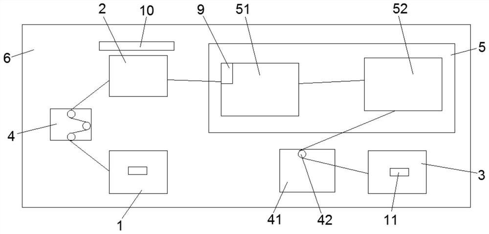
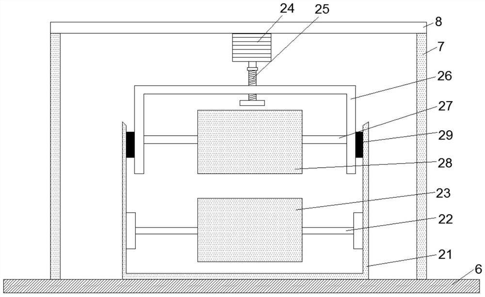
[0020]ReferFigure 1 to 2As shown, an embodiment of a multi-function coater of the present invention includes a discharge device 1, a coating device 2, and a winding device 3, and a coating device 1, and a coating device 2, coating. A traction device 4 is provided between the cloth device 2 and the winding apparatus 3, and the coating device 2 and the winding device 3 are also provided with a drying device 5, and the drying device 5 includes a preheating oven 51 and drying. Box 52; the coating device 2 includes a tank 21, and the inner wall of the binder 21 is adjacent to the bottom, and the first spindle 22 is mounted by the bearing, and the first spindle 22 is provided with an upper liquid roller 23, and the tank 21 is disposed at work. On the table 6, th...


PUM


Abstract

The invention discloses a multifunctional coating machine. The multifunctional coating machine comprises an unwinding device, a coating device and a winding device which are sequentially arranged, traction devices are arranged between the unwinding device and the coating device and between the coating device and the winding device, and a drying device is further arranged between the coating deviceand the winding device. The drying device comprises a preheating oven and a drying box which are arranged in sequence. The coating device comprises a trough, first rotating shafts are installed at the positions, close to the bottom, of the inner walls of the two sides of the trough through bearings, liquid feeding rollers sleeve the first rotating shafts, the trough is arranged on a workbench, alifting block is arranged on a lead screw, a second rotating shaft is arranged in the middle of the lifting block, and a pressing roller sleeves the second rotating shaft. Moving rails are arranged atthe positions, close to the lifting block, in the two sides of the trough, limiting plates are arranged on the two sides of the lifting block, and the limiting plates can move in the moving rails. The multifunctional coating machine is simple in structure and good in gluing effect and can be suitable for coating of paper with different thicknesses, and meanwhile the rate of finished products canbe increased through the arranged drying device.

Description

Technical field[0001]The present invention relates to the field of coating machines, and more particularly to a multifunctional coating machine.Background technique[0002]The coater is mainly used for the surface coating process of films, paper, and the like, which is a layer of specific functional glue, paint or ink, or the like, and dry after drying.[0003]At the time of operation, the coating machine usually coat the coating between the coatings between them, but because the gap between the two rollers is fixed due to the working process, first When needed to apply a different thickness, the spacing between the two rollers cannot be adjusted, resulting in limiting the applicability of the coater, and the workpiece of different thicknesses requires different types of coating machines, high use cost. And the existing coater is applied to the rear tank to the oven distance too long, the coating is applied to the workpiece and then erosion from the cold air into the first hollow, the c...

Claims


Application Information

Patent Timeline
IPC IPC(8): B05C1/08B05C9/14B05C13/02
CPCB05C1/0808B05C1/0834B05C9/14B05C13/02
Inventor 黄友斌
Owner 江苏精屯机电设备有限公司
Why Eureka
Try Eureka