Ultrasonic cleaning device

A cleaning device and ultrasonic cleaning technology, applied in the field of ultrasonic cleaning, can solve the problems of reduced cleaning effect, damage to the ultrasonic cleaning device, and inability to remove dust and stains in advance, so as to avoid waste of manpower and water resources.

Inactive Publication Date: 2021-03-19
张家港三能机电设备有限公司
View PDF5 Cites 2 Cited by
  • Summary
  • Abstract
  • Description
  • Claims
  • Application Information

AI Technical Summary

Problems solved by technology

[0004] When the existing ultrasonic cleaning device is used, it lacks a pretreatment process, and the dust and stains on the surface of the parts cannot be removed in advance, which will easily cause damage to the ultrasonic cleaning device and reduce the cleaning effect. Therefore, an ultrasonic cleaning device is invented to solve the problem. above question

Method used


Image

  • Ultrasonic cleaning device
  • Ultrasonic cleaning device
  • Ultrasonic cleaning device

Examples


Embodiment 1

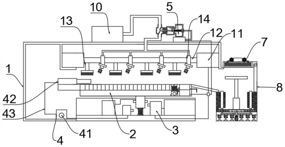
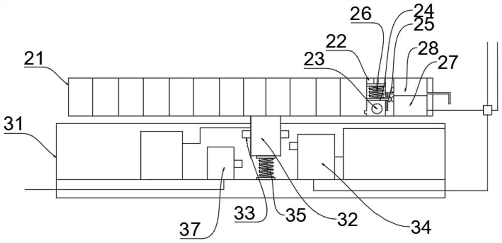
[0030] refer to Figure 1-5 , an ultrasonic cleaning device, comprising a body 1, a cleaning device 2 and a control device 3, an ultrasonic cleaning device 8 is arranged on the side of the cleaning device 2, and a motor 11 and a rotating shaft 12 are arranged above the cleaning device 2, and the rotating shaft 12 is connected to the The output ends of the motor 11 are connected, and the side of the rotating shaft 12 is connected with several roller brushes 13, and the side of the rotating shaft 12 is slidingly connected with several nozzles 14, and the nozzles 14 are connected with a water control device arranged on the top of the fuselage 1 through water pipes 5, and the side of the water control device 5 is connected to the water tank 10 through a water pipe, the cleaning device 2 includes a cleaning table 21 and a return cavity 22 arranged inside the cleaning table 21, and the inside of the cleaning table 21 is provided with several through holes, and the through holes are c...

Embodiment 2

[0038] refer to Figure 6 , an ultrasonic cleaning device, compared with Embodiment 1 in this embodiment, the drying device 7 includes a drying chamber 71 and a filter screen 72 arranged inside the drying chamber 71, and a heating wire 73 is arranged below the filter screen 72 , Two blowers 74 are arranged above the drying chamber 71 .

[0039] Working principle: when in use, the drying device 7 is provided to facilitate drying when the ultrasonic cleaning is completed, so as to ensure that the parts are in a dry state, which is beneficial to the preservation of the parts, and the filter 72 is provided to ensure the cleanness of the air during use.


PUM


Abstract

The invention discloses an ultrasonic cleaning device. The ultrasonic cleaning device comprises a machine body, a cleaning device body and a control device, wherein the ultrasonic cleaning device bodyis arranged on the side face of the cleaning device body, a motor and a rotating shaft are arranged above the cleaning device body, the rotating shaft is connected to the output end of the motor, a plurality of rolling brushes are connected to the side face of the rotating shaft, the side face of the rotating shaft is slidably connected to a plurality of spray heads, the spray heads are connectedto a water control device arranged above the machine body through a water pipe, the side face of the water control device is connected to a water tank through a water pipe, and a cleaning device comprises a cleaning table and a backflow cavity formed inside the cleaning table. According to the ultrasonic cleaning device, when in use, by arranging the cleaning device, parts needing to be cleaned can be conveniently pretreated in the using process, sludge and chippings of the parts are prevented from entering the interior of the ultrasonic cleaning device and damaging the ultrasonic cleaning device, and by arranging a control device, the whole cleaning process can be conveniently controlled to be conducted in order.

Description

technical field [0001] The invention relates to the technical field of ultrasonic cleaning, in particular to an ultrasonic cleaning device. Background technique [0002] Ultrasonic cleaning is to use the cavitation, acceleration and direct flow of ultrasonic waves in the liquid to directly and indirectly affect the liquid and dirt, so that the dirt layer is dispersed, emulsified, and peeled off to achieve the purpose of cleaning. [0003] Ultrasonic cleaning technology has developed greatly in the 1950s, when the ultrasonic working frequency used was between 20 and 40kHz. Ultrasonic waves in this range are used in thousands of different workplaces, many of which are where other cleaning methods do not work well. Ultrasonic waves can apply very large amounts of energy to workpieces, and are especially useful for removing dirt firmly attached to substrates. However, in some cases, the powerful energy of ultrasonic waves can also damage the fragile base material with dirt. I...

Claims


Application Information

Patent Timeline
Patent Type & Authority Applications(China)
IPC IPC(8): B08B1/02B08B1/00B08B3/02B08B13/00B08B9/087B08B3/12F26B9/06F26B21/00
CPCB08B1/02B08B1/002B08B3/022B08B13/00B08B9/087B08B3/12F26B9/066F26B21/001F26B21/003F26B21/004
Inventor 丁晓波
Owner 张家港三能机电设备有限公司
Why Eureka
Try Eureka