
Rotary ic card punching and milling equipment

A rotary and blanking technology, which is applied in metal processing equipment, other manufacturing equipment/tools, manufacturing tools, etc., can solve the accumulation of coaxiality errors in card milling slots, out-of-tolerance groove size surface finish, and out-of-tolerance coaxiality Scrap and other issues, to achieve the effect of improving product qualification rate, high dimensional accuracy and surface finish, and ensuring dimensional accuracy

Active Publication Date: 2022-07-22
宁波阅荷思山智能科技有限公司
View PDF5 Cites 0 Cited by
  • Summary
  • Abstract
  • Description
  • Claims
  • Application Information

AI Technical Summary

Problems solved by technology

[0003] The existing single-station IC card slot milling machine can only process a single slot, and the processing efficiency is low. The processing efficiency of the multi-station slot milling machine is relatively high, but the relative positions of the spindles of each station are fixed, relying on the same set of displacement The mechanism controls the slot milling trajectory, and each complete slot milling process is completed by the same milling cutter. When the wear of the milling cutter is inconsistent, the processed slot size and surface finish are often out of tolerance
In addition, in the existing card production, cutting and slot milling are carried out on two devices. The slot milling machine uses a single card belt feeding, which is inefficient and requires repeated positioning when the station is changed. Repeated positioning makes the card The concentricity error of milling slots continues to accumulate, resulting in the scrapping of the final product due to the out-of-tolerance concentricity

Method used


Image

  • Rotary ic card punching and milling equipment
  • Rotary ic card punching and milling equipment
  • Rotary ic card punching and milling equipment

Examples


Embodiment Construction

[0038] The present invention will be described in further detail below with reference to the accompanying drawings and specific embodiments, but the scope of implementation of the present invention is not limited thereto.

[0039]The material tape used for making the card used in this embodiment is supplied in the form of a material roll, which includes an unwinding roll and a rewinding roll, so as to facilitate the continuous supply of raw materials.

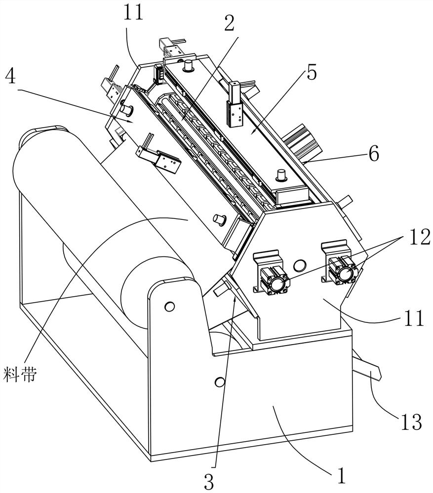
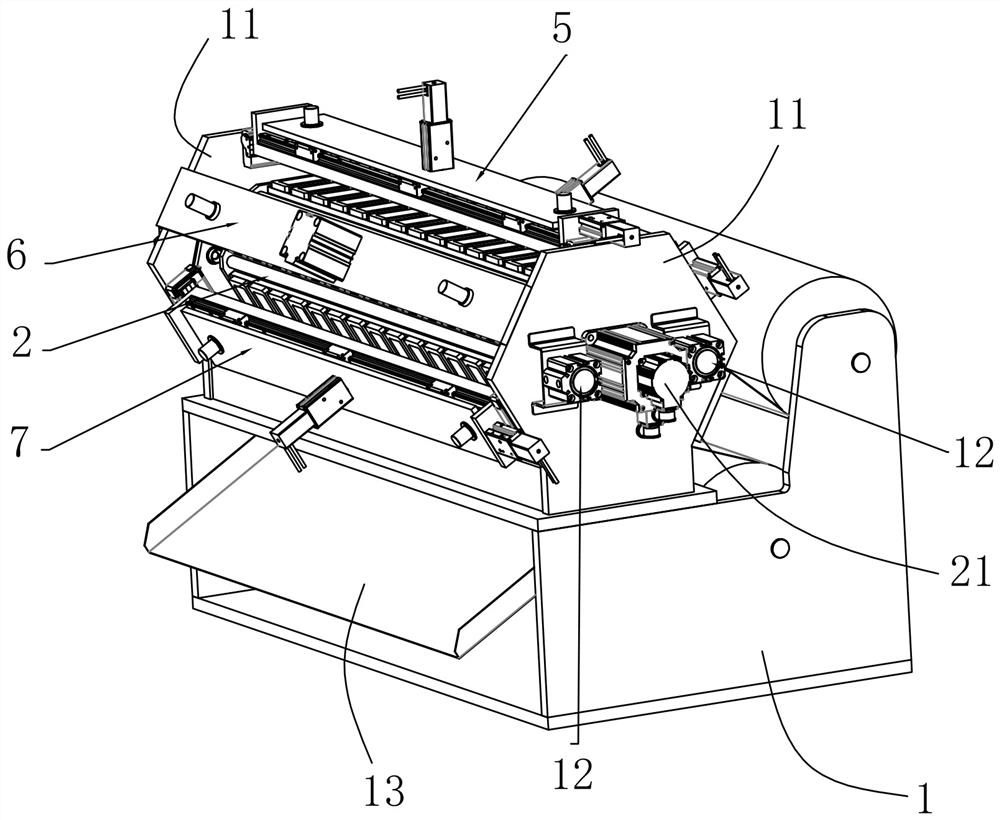
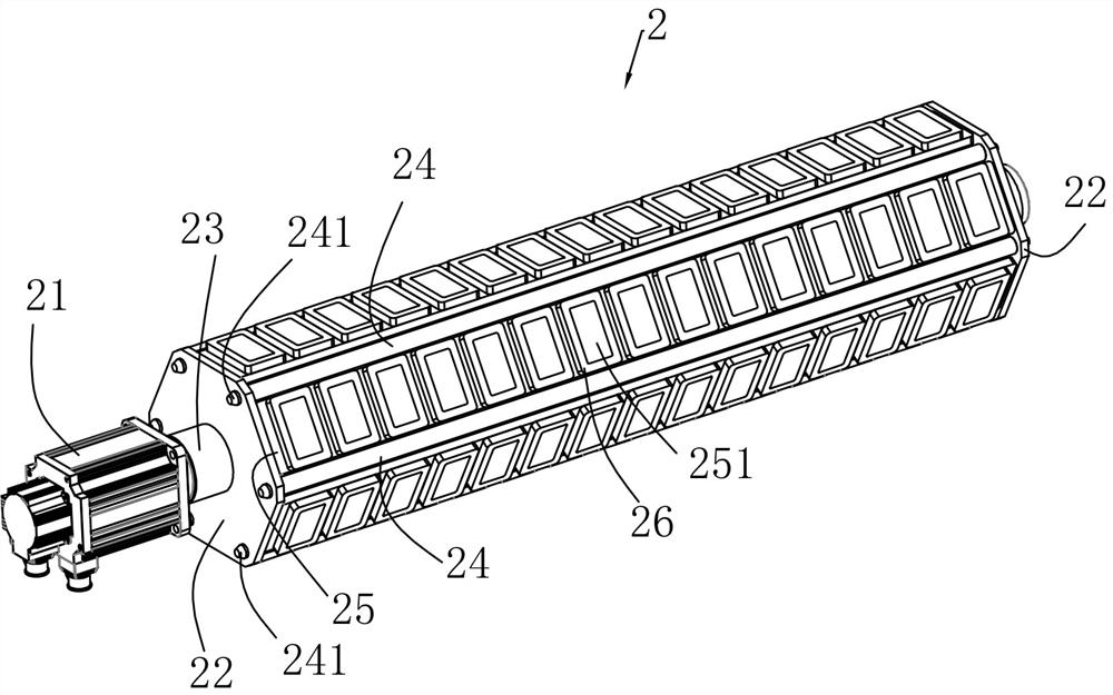
[0040] like Figure 1 to Figure 9 As shown, a rotary IC card punching and milling device described in this embodiment includes a frame 1, and the frame 1 has two side plates 11 in the shape of regular hexagons and arranged opposite to each other. The side plates 11 are all provided with a positioning mechanism 12; it also includes a station rotation mechanism 2 rotatably connected between the middle parts of the two side plates 11 and in the form of a regular hexagonal prism, and a position rotation mechanism 2 corresponding to...


PUM


Abstract

The invention discloses a rotary IC card punching and milling equipment, comprising a frame, the frame is provided with two regular hexagon-shaped side plates arranged opposite to each other, and the two side plates are both provided with positioning mechanisms; A station rotating mechanism rotatably connected between the middle parts of the two side plates and in the form of a regular hexagonal column, and a card cutting station and a square groove rough milling station correspondingly arranged between the opposite sides of the two side plates in the circumferential direction. , square groove fine milling station, square groove size detection station, circular groove milling station; the invention forms a rotary multi-station cyclic operation, realizes the combination of card cutting, rough milling, fine milling and detection, and has high production efficiency , The dimensional accuracy and surface finish are higher, so that the product qualification rate is greatly improved, no repeated positioning is required, the accumulation of repeated positioning errors is avoided, and the dimensional accuracy of the square groove is guaranteed.

Description

technical field [0001] The invention relates to a rotary IC card punching and milling device. Background technique [0002] IC card, also known as integrated circuit card, is an information record carrier formed by embedding one or more integrated circuits on a plastic card with a size of 85.6mm × 54mm. The general structure of an IC card is that an IC chip is included in the card. The processing process is as follows: first, a square recess with rounded corners is milled at a certain position of the IC card, and then a circle is coaxially milled in the middle of the square recess. There is a circular seal on the inner side of the IC chip, which seals and fixes the IC chip, so when making an IC card, the contour edge of the square concave There are strict machining accuracy requirements for the depth and depth, but the diameter and depth of the circular recess are not strict. [0003] The existing single-station IC card slot milling machine can only process a single slot, ...

Claims


Application Information

Patent Timeline
Patent Type & Authority Patents(China)
IPC IPC(8): B23P23/04B23Q3/06
CPCB23P23/04B23Q3/06
Inventor 沐旭
Owner 宁波阅荷思山智能科技有限公司
Learn More