Band sawing machine for production of furniture

A band sawing machine and furniture technology, applied in band saws, sawing components, manufacturing tools, etc., can solve the problems of inability to cut wood at different angles, high safety hazards, etc., to reduce the number of placements, ensure safety, reduce costs and The effect of space occupancy

Pending Publication Date: 2021-03-19
浙江荣涛家具有限公司
View PDF6 Cites 1 Cited by
  • Summary
  • Abstract
  • Description
  • Claims
  • Application Information

AI Technical Summary

Problems solved by technology

[0004] Aiming at the deficiencies of the prior art, the present invention provides a band sawing machine for furniture production, which solves the problem of high safety hazards caused by manual contact with wood and pushing wood for cutting, and the problem that wood cannot be cut at different angles

Method used


Image

  • Band sawing machine for production of furniture
  • Band sawing machine for production of furniture
  • Band sawing machine for production of furniture

Examples


Embodiment 1

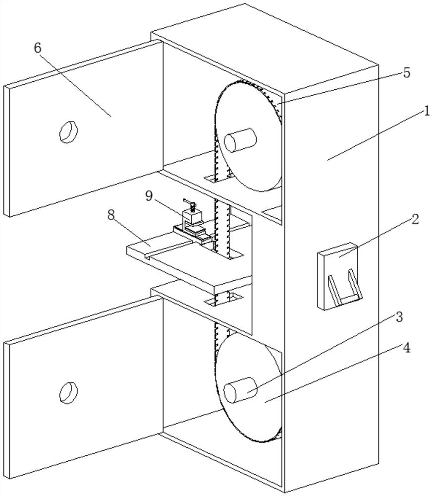
[0030] A band sawing machine for furniture production, such as Figure 1-Figure 5 As shown, it includes a box body 1, the right side of the box body 1 is connected with a switch knife 2 by bolts, the inner wall of the box body 1 is rotatably connected with two rotating shafts 3, the surface of the rotating shaft 3 is clamped with a turntable 4, and the two turntables 4 The surface is connected through the transmission of the saw band 5, the inner wall of the box body 1 is rotatably connected with two revolving doors 6, and the inner wall of the revolving door 6 is rotatably connected with the surface of the rotating shaft 3, the inside of the box body 1 is provided with a transmission mechanism 7, and the box body 1 The surface of the table is rotatably connected with a workbench 8, and the surface of the workbench 8 is provided with a fixing mechanism 9.

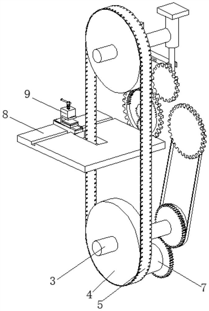
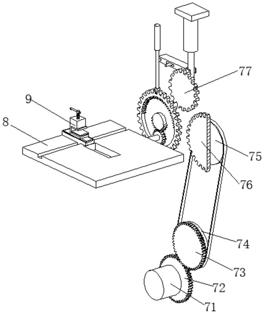
[0031] In this embodiment, the transmission mechanism 7 includes a motor 71, the output end of the motor 71 is clamped wi...

Embodiment 2

[0040] Such as Figure 5-Figure 7 As shown, on the basis of Embodiment 1, in this embodiment, the surface of the slide plate 92 is slidingly connected with the inner wall of the slide block 95, and the top of the fixed block 91 is provided with a mounting device 93, and the slide plate 92 can be moved left and right on the slide block 95. Sliding, so that the cutting position can be adjusted freely, the practicability is greatly increased, the operation is convenient and simple, and it is beneficial to popularize and use.

[0041] The installation device 93 includes a screw rod 931, the inside of the screw rod 931 is movably connected with a push rod 932, the bottom end of the screw rod 931 is rotatably connected with an upper pressing plate 933, the inner wall of the slide plate 92 is movably connected with a fixed spring 935, and the top of the fixed spring 935 is welded with a fixed Column 934, the top of the fixed column 934 is welded with a lower pressure plate 936.

[0...


PUM


Abstract

The invention relates to the technical field of furniture, and discloses a band sawing machine for production of furniture. The band sawing machine comprises a box body, wherein a switch blade is connected to the right side of the box body through bolts; two rotating shafts are rotatably connected to the inner wall of the box body; rotary discs are clamped on the surfaces of the rotating shafts; the surfaces of the two rotary discs are in transmission connection with each other through a saw band; two revolving gates are rotatably connected to the inner wall of the box body; a transmission mechanism is arranged in the box body; a worktable is rotatably connected to the surface of the box body; and a fixed mechanism is arranged on the surface of the worktable. According to the band sawing machine disclosed by the invention, wood can be clamped by using a clamp through the fixed mechanism, and can be cut through pushing the clamp, and thus, hands are not needed to directly contact the wood, the wood can be pushed and then cutting of the wood can be performed, so that cutting of the wood at different angles can be realized, and the working range of the device is widened.

Description

technical field [0001] The invention relates to the technical field of furniture, in particular to a band sawing machine for furniture production. Background technique [0002] Furniture refers to the essential equipment and facilities for human beings to maintain normal life, engage in production practice and carry out social activities. Furniture also follows the pace of the times and continues to develop and innovate. Up to now, there are many categories, different materials, complete varieties, and different uses. , is an important foundation for building a working and living space. [0003] At present, the band sawing machine is directly in contact with the wood by hand and pushes it to cut, which has a high potential safety hazard. The workers may cause safety accidents due to temporary negligence, and the existing band sawing machine can only cut the wood vertically. Cutting can not cut the wood at a certain angle, and the practicality is low. Therefore, a band sawin...

Claims


Application Information

Patent Timeline
Patent Type & Authority Applications(China)
IPC IPC(8): B27B13/00B27B13/04B27B13/14B27B13/16B27B25/10B27B29/02
CPCB27B13/00B27B29/02B27B13/04B27B13/16B27B25/10B27B13/14
Inventor 王波
Owner 浙江荣涛家具有限公司
Why Eureka
Try Eureka