
A wind-resistant and shock-proof ceiling structure and construction method in the track area of ​​urban rail elevated station

A technology of track area and suspended ceiling, applied in the direction of building structure, ceiling, building components, etc., can solve problems such as unsatisfactory

Active Publication Date: 2021-07-06
广东省建筑装饰工程有限公司
View PDF7 Cites 0 Cited by
  • Summary
  • Abstract
  • Description
  • Claims
  • Application Information

AI Technical Summary

Problems solved by technology

The traditional indoor ceiling structure cannot meet the technical requirements of the current elevated station ceiling, which is an urgent technical problem to be solved for the interior decoration of urban rail transit elevated stations

Method used


Image

  • A wind-resistant and shock-proof ceiling structure and construction method in the track area of ​​urban rail elevated station
  • A wind-resistant and shock-proof ceiling structure and construction method in the track area of ​​urban rail elevated station
  • A wind-resistant and shock-proof ceiling structure and construction method in the track area of ​​urban rail elevated station

Examples


Embodiment 1

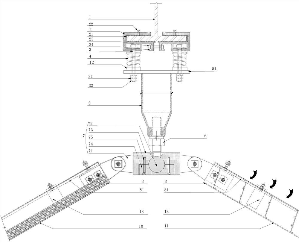
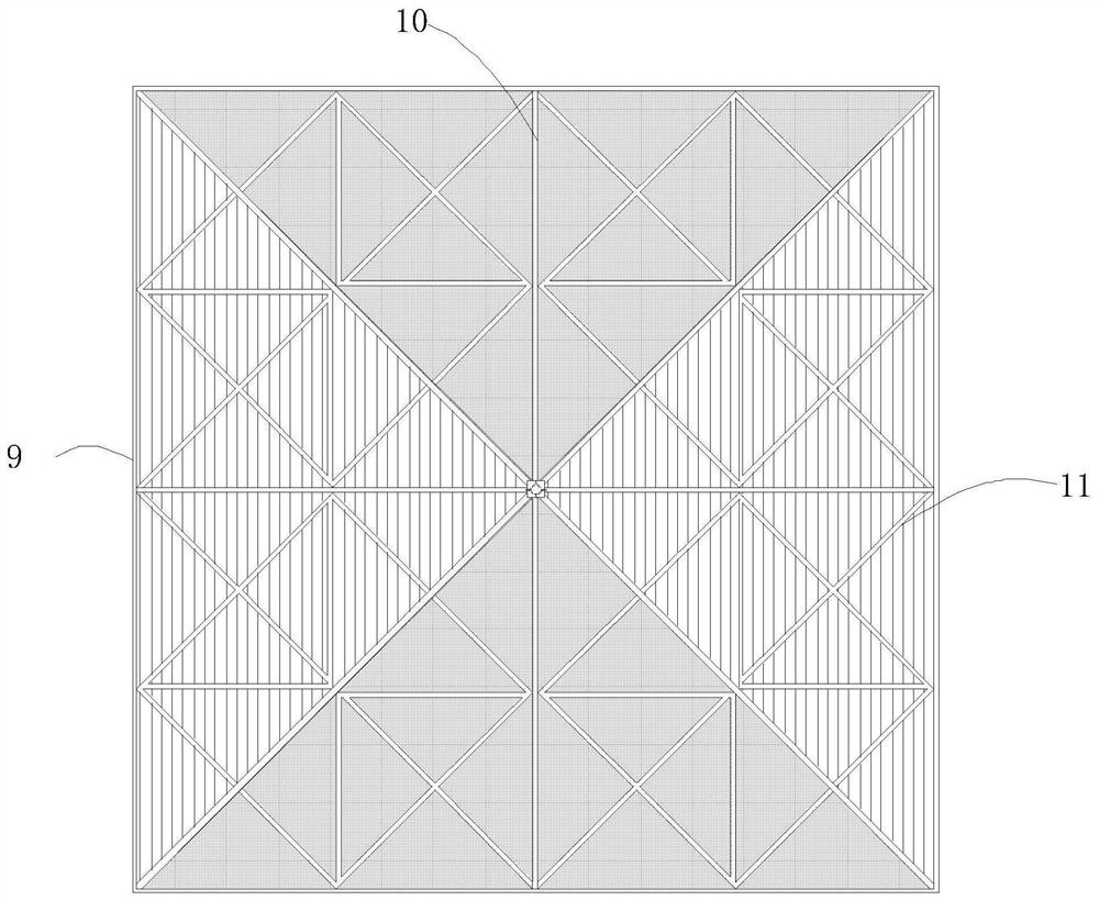
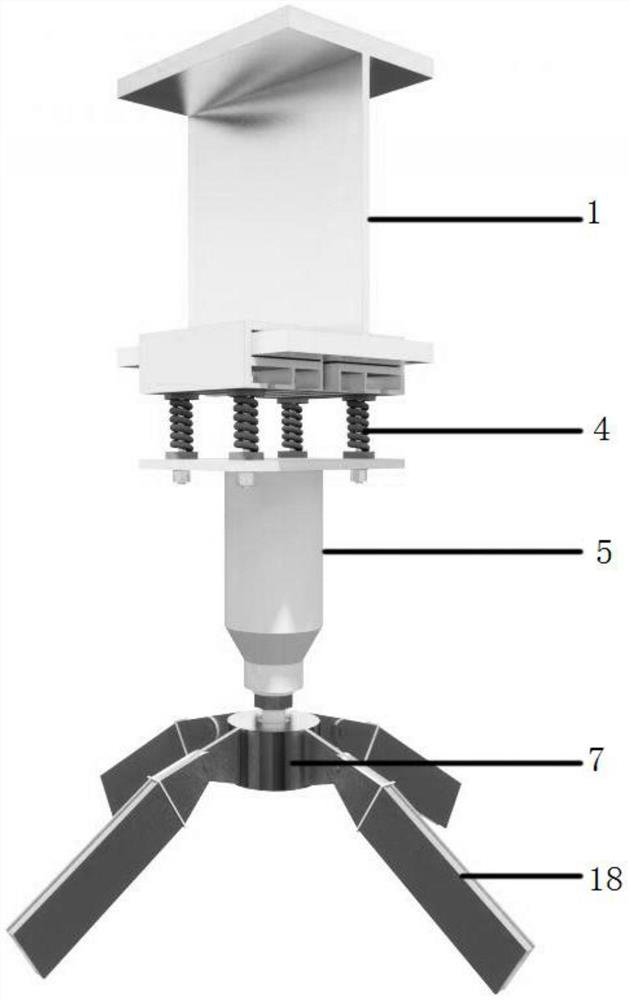
[0046] refer to Figure 1-8 As shown, the anti-pipe-narrow effect four-cone ceiling structure in the track area provided by this embodiment includes I-beam 1, and hoops 2 are respectively arranged on both sides of the lower leg steel beam of I-beam, as shown in Figure 3-6 As shown, the hoop 2 can be adjusted and fixed along the length direction of the steel beam of the I-beam lower leg, that is to say, the hoop 2 can be adjusted forward and backward along the steel beam, which is "three-dimensional adjustable" front and rear adjustment.

[0047] A shock absorber bolt groove is arranged in the hoop 2, a shock absorber bolt 3 is sheathed in the shock absorber bolt groove, a shock absorber 4 is inserted in the shock absorber bolt 3, and the shock absorber bolt 3 The end is put through the goose egg bolt hole 510 of the support column base 51 and fastened by the nut 31, as Figure 4 As shown, since the goose egg bolt hole 510 has a certain lateral gap distance, that is, the shoc...

Embodiment 2

[0058] This embodiment provides a construction method for a four-pyramid-shaped suspended ceiling that resists tube narrowing effect in the track area, which is applied to the suspended ceiling structure of the above-mentioned embodiment 1. The method includes the steps of:

[0059] Positioning and setting-out steps:

[0060] Using the total station, according to the current situation of the network frame in the track area, first set a reference line on the ball node of the network frame, and then determine the position of the control lines on both sides through the reference line; respectively locate the center line between the beams , the intersection of the longitudinal centerline and each transverse centerline is the hoop positioning point;

[0061] According to the actual height of the finished surface of the platform ceiling, determine the bottom height of the ceiling in the track area, and calculate the top elevation and slope of the ceiling; re-deepen the design after ...


PUM


Abstract

The invention discloses a wind-resistant and shock-proof suspended ceiling structure and a construction method in the track area of ​​an elevated station of urban rail. Shock absorber bolt groove, the shock absorber bolt is sheathed in the shock absorber bolt groove; the support column is rigidly connected in the middle; it also includes four main keels, four side keels and universal joint flanges to form a four-cone assembly Type keel structure, four triangular unit assembly areas are formed between the four main keels and the four side keels, and the four triangular unit assembly areas are respectively equipped with perforated sound-absorbing panel triangular units and aluminum louver triangular units. The structure of the ceiling adopts the triangular unit formed by punching sound-absorbing panels and aluminum strip louvers in the processing plant, and is hoisted on site to form a "four-cone" ceiling, which meets the requirements of lighting, sound absorption, decorative space, and beautiful decoration, and reduces the "tube narrow effect". The impact of walking vibration and earthquake action on the suspended ceiling.

Description

technical field [0001] The invention relates to the field of building construction, in particular to a structure and a construction method for a wind-resistant and shock-proof suspended ceiling in a track area of ​​an elevated station of urban rail. Background technique [0002] With the rapid development of my country's urban rail transit and the improvement of people's living standards, more and more elevated station rail areas and waiting areas are decorated with ceilings. At the same time, the distribution of elevated stations is also extended to high-intensity earthquake areas and coastal typhoon areas. [0003] The ceiling of the elevated station will be affected by the narrow tube effect, the vibration of the high-speed train and the potential earthquake threat, especially the strong narrow tube effect wind in the coastal typhoon area and the earthquake in the high-intensity earthquake area will easily cause the ceiling in the track area to fall or The collapse will c...

Claims


Application Information

Patent Timeline
Patent Type & Authority Patents(China)
IPC IPC(8): E04B9/06E04B9/18E04B9/34E04G21/14
CPCE04B9/061E04B9/18E04B9/34E04B9/345E04B2009/186E04G21/14
Inventor 蓝建勋曾金亮
Owner 广东省建筑装饰工程有限公司
Learn More