
A hydrodynamic propulsion device

A propulsion device and hydrodynamic technology, which is applied to pump devices, electromechanical devices, and components of pumping devices for elastic fluids, etc. Economic cost saving effect

Active Publication Date: 2022-07-15
ZHEJIANG UNIV OF TECH
View PDF4 Cites 0 Cited by
  • Summary
  • Abstract
  • Description
  • Claims
  • Application Information

AI Technical Summary

Problems solved by technology

[0004] In order to solve the above-mentioned technical problems existing in the prior art, the object of the present invention is to provide a hydrodynamic propulsion device, which can effectively meet the requirements of obtaining a relatively large flow rate at a relatively low propulsion speed, realize water body propulsion, and accelerate the fluidity of river water flow; the device It replaces the work of the pumping station and at the same time saves a lot of unnecessary economic loss compared with the establishment of the pumping station; at the same time, the moving speed of the blades is small, the operation of the device is relatively stable, the hydraulic performance can be greatly improved, and the pumping station is avoided. The problem of high energy consumption when operating under low lift can well complete the water propulsion work in the plain capillary river network; the low-speed blades can also avoid damage to over-current organisms and achieve eco-friendliness

Method used


Image

  • A hydrodynamic propulsion device
  • A hydrodynamic propulsion device
  • A hydrodynamic propulsion device

Examples


Embodiment Construction

[0022] The present invention will be further described below with reference to the accompanying drawings.

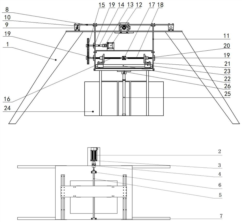
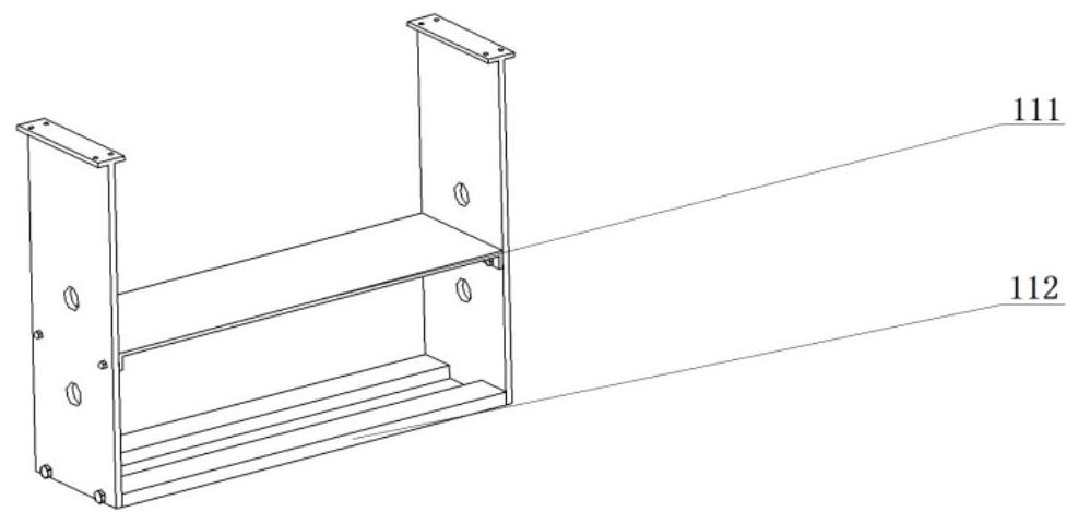
[0023] refer to Figure 1 to Figure 7 , a hydrodynamic propulsion device, comprising an upper platform 1 and a lower platform 11, the upper platform 1 is built with a longitudinal displacement drive motor 2, and the longitudinal displacement drive motor 2 is fixed to the upper platform 1 through a motor connecting plate 3, The motor shaft is connected with the lead screw 5 through the coupling 4, and the two ends of the lead screw 5 are fixed by the fixed-side standard lead-screw support 6 and the support-side standard lead-screw support 7, and the lead screw 5 drives the moving plate 8 moves. A guide rail 9 and a sliding block 10 are fixed on the upper platform, the moving plate 8 is fixed with the sliding block 10, and the lead screw 5 and the moving plate 8 realize longitudinal linear reciprocation on the upper platform 1 sports;

[0024] The lower platform 11 is f...


PUM


Abstract

A hydrodynamic propulsion device includes an upper platform and a lower platform, the upper platform is built with a longitudinal displacement driving motor, a guide rail and a slider mechanism are fixed, and a lead screw drives a moving plate to realize longitudinal linear reciprocating motion on the upper platform; The plate is fixed, the horizontal displacement drive motor is fixed on the upper layer of the lower platform, and the lower guide rail slider mechanism is fixed on the lower layer of the lower platform. The connecting plate, the lower slider and the moving blade reciprocate linearly in the same direction or different directions at the same time, the moving blade is matched with the middle fixed blade, and the middle fixed blade is fixed with the lower platform through the blade fixing plate. The invention effectively satisfies the requirement of obtaining a larger flow at a lower driving speed, and accelerates the fluidity of the river flow; saves a lot of unnecessary economic losses; avoids the problem of high energy consumption caused by the operation of the pump station at a low head, and also avoids the problem of high energy consumption. The harm of over-flowing organisms to achieve eco-friendliness.

Description

technical field [0001] The invention belongs to the technical field of hydrodynamic propulsion, and in particular relates to a hydrodynamic propulsion device. Background technique [0002] The terrain of the plain is low and flat, and the hydraulic gradient in the upstream and downstream is extremely small. Some capillary-shaped channels lack water supply and insufficient water flow. The impact of human beings on the river channels within the residential area is becoming more and more obvious. The construction of cities has changed the natural form of the river channels, resulting in the shrinking of the river network, the decline in connectivity, and the weakening of the capacity for regulation and storage. In addition, a large amount of domestic and industrial sewage is discharged. into the river, aggravating the water quality deterioration and ecological environment degradation of the river in the plain city limits. Therefore, the fluidity of river water flow is an urgen...

Claims


Application Information

Patent Timeline
Patent Type & Authority Patents(China)
IPC IPC(8): F04D13/06F04D29/18H02K7/116H02K7/06
CPCF04D13/06F04D29/18H02K7/116H02K7/06
Inventor 汤守伟华尔天陈万前郭晓梅徐高欢谢荣盛陈仙明周昌全
Owner ZHEJIANG UNIV OF TECH
Learn More