
Laver drying equipment

A technology of drying equipment and seaweed, which is applied in drying, drying machines, lighting and heating equipment, etc., and can solve the problems of external crispness and internal moisture, great influence of humidity, heat loss, etc.

Pending Publication Date: 2021-03-19
陈进车
View PDF0 Cites 1 Cited by
  • Summary
  • Abstract
  • Description
  • Claims
  • Application Information

AI Technical Summary

Problems solved by technology

[0002] Existing large-scale laver drying equipment is mainly composed of a large drying room connected with a heating device. Multiple racks are placed in the large drying room, and wet laver to be dried is loaded on the racks. The fan evenly transmits the heat in the large drying room to various positions in the large drying room. Because the temperature in the drying room is high and the wind is strong, it is usually necessary to add a new one every time. Wet laver racks, at the same time push out a dried rack from the rear, such a way of one in and one out, but there are defects in this drying equipment, one is that the wet laver is directly dried at high temperature when the humidity is high , it is easy to form external dryness and internal dampness or external crispness and internal moisture. Second, laver needs to absorb more oxygen to fully oxidize during the initial drying process from high humidity to semi-dry, so as to ensure that the dried laver is shiny. The selling image of the finished product will be better, and laver does not need additional oxygen to oxidize during the post-drying process from half-dry to full-dry. The traditional method for this is to directly add air in the large drying room , while the laver drying process is mostly in winter, directly adding air will cause a large loss of heat in the large drying room, greatly increasing the energy loss of the heating equipment, and the added wet laver emits a large amount during the drying process Moisture, under the blowing of a large fan, circulates together with the hot air in the drying room, which has a greater impact on the humidity in the drying room, and increases the overall drying time for the seaweed that entered the drying room to be completely dry.

Method used


Image

  • Laver drying equipment
  • Laver drying equipment
  • Laver drying equipment

Examples


Embodiment Construction

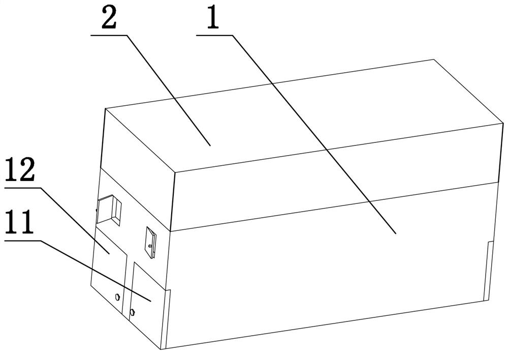
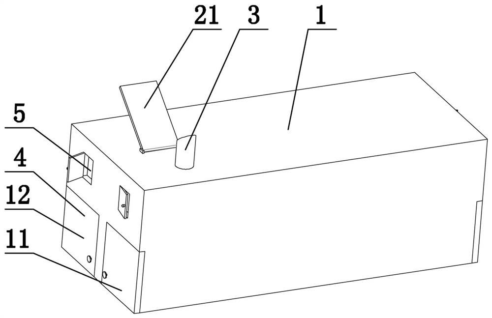
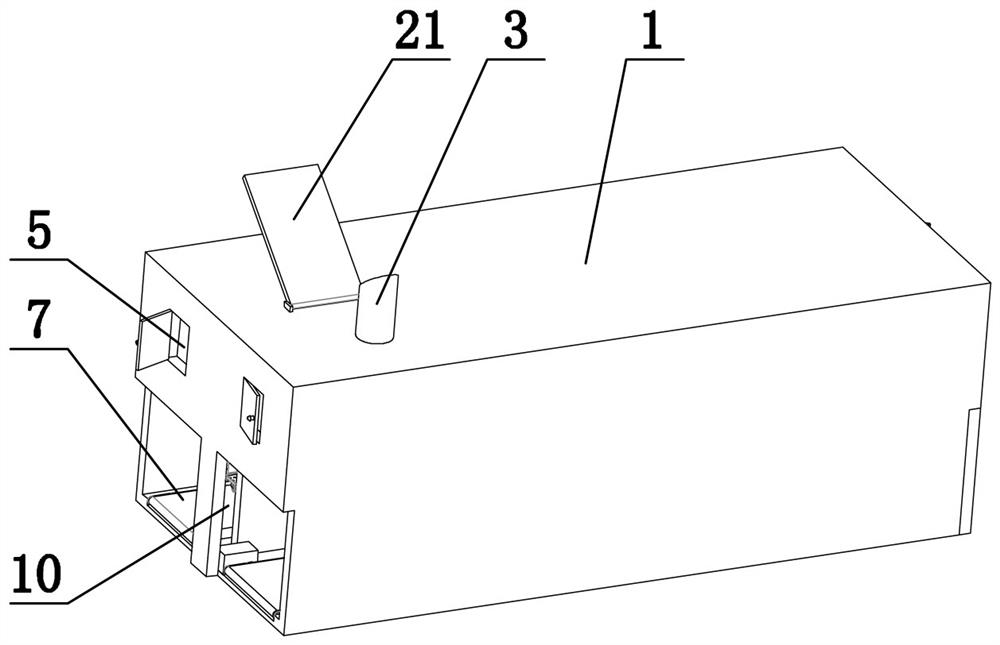
[0020] Such as Figure 1-5 As shown, the laver drying equipment provided by the present invention includes heating equipment, a heating pipeline and a drying room 1. The heat generated by the heating equipment is transmitted to the drying room 1 through the heating pipeline. It is characterized in that: the drying room 1 is equipped with a high temperature Room 2, the drying room 1 includes a first drying room 11 and a second drying room 12, the first drying room 11 and the second drying room 12 are equipped with an air inlet pipe 3, a front door 4, an air intake window 5, an exhaust Window 6, conveyer belt 7, circulation fan 8 and several storage racks 9, also be provided with ventilation door 10 between the first drying room 3 and the second drying room 4, described air inlet duct 3 is communicated with high temperature chamber 2, the first A baffle plate 21 is also provided between the air inlet pipe 3 of the drying room 11 and the air inlet pipe 3 of the second drying room...


PUM


Abstract

Laver drying equipment comprises heating equipment, heating pipelines and drying rooms, wherein heat generated by the heating equipment is transmitted into the drying rooms through the heating pipelines, a high-temperature room is arranged outside each drying room, the drying rooms comprise a first drying room and a second drying room, each of the first drying room and the second drying room is provided with an air inlet pipe, a front door, an air inlet window, an exhaust window, a conveying belt, a circulating fan and a plurality of storage racks, a ventilation door is further arranged between the first drying room and the second drying room, each air inlet pipe communicates with the corresponding high-temperature room, a baffle plate is further arranged between the air inlet pipe of thefirst drying room and the air inlet pipe of the second drying room, and the baffle plate controls the communication between the air inlet pipes and the high-temperature rooms. The laver drying equipment has the advantages of saving energy, saving processing time and being good in finished product processing effect.

Description

technical field [0001] The invention relates to laver drying equipment, in particular to a large laver drying equipment. Background technique [0002] Existing large-scale laver drying equipment is mainly composed of a large drying room connected with a heating device. Multiple racks are placed in the large drying room, and wet laver to be dried is loaded on the racks. The fan evenly transmits the heat in the large drying room to various positions in the large drying room. Because the temperature in the drying room is high and the wind is strong, it is usually necessary to add a new one every time. Wet laver racks, at the same time push out a dried rack from the rear, such a way of one in and one out, but there are defects in this drying equipment, one is that the wet laver is directly dried at high temperature when the humidity is high , it is easy to form external dryness and internal dampness or external crispness and internal moisture. Second, laver needs to absorb more...

Claims


Application Information

Patent Timeline
IPC IPC(8): F26B9/10F26B21/04F26B25/06F26B25/18A23N12/08
CPCF26B9/10F26B21/001F26B21/004F26B21/04F26B25/06F26B25/18A23N12/08F26B2200/16Y02P60/85
Inventor 陈进车
Owner 陈进车
Learn More