Airflow sensor and oleophobic and hydrophobic treatment method

An airflow sensor and hydrophobic treatment technology, applied in the field of sensors, can solve the problems of not being able to pass through the airflow sensor, block the air holes of the dust-proof net, reduce the service life of electronic cigarettes, etc., and achieve the effect of simple process and short drying time

Pending Publication Date: 2021-03-19
YANTAI NIVO NEW MATERIAL CO LTD
View PDF0 Cites 3 Cited by
  • Summary
  • Abstract
  • Description
  • Claims
  • Application Information

AI Technical Summary

Problems solved by technology

[0005] Take the e-cigarette using the above-mentioned airflow sensor as an example. During the working process, the e-cigarette will form condensed e-liquid and the e-liquid leaked from the pod. Make it not work properly, causing it to malfunction, greatly reducing the service life of the electronic cigarette
[0006] In order to solve the above-mentioned technical problems, generally, those skilled in the art arrange one deck dust-proof net 13 on the air inlet 3, the airflow hole 2 of airflow sensor, yet, its improvement effect is limited, and there are still problems, such as Figure 4 , Figure 5 As shown, liquid r...

Method used


Image

  • Airflow sensor and oleophobic and hydrophobic treatment method
  • Airflow sensor and oleophobic and hydrophobic treatment method
  • Airflow sensor and oleophobic and hydrophobic treatment method

Examples


Embodiment 1

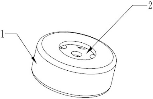
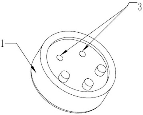
[0047] Example 1, such as figure 1 , 2 , 6 and 8, an airflow sensor includes an airflow sensor body 1, the airflow sensor body 1 is a hollow cylindrical tube, the top of the airflow sensor body 1 is provided with an airflow hole 2, and the bottom of the airflow sensor body 1 is provided with an air inlet 3. An air outlet protective film 4 is fixed on the airflow hole 2, and the air outlet protective film 4 just covers the top of the airflow sensor body 1, and an air inlet protective film 5 is fixed on the air inlet 3, and the air inlet protective film 5 just covers the top of the airflow sensor body 1. Air intake hole 3.

Embodiment 2

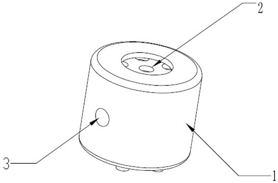
[0048] Example 2, such as image 3 , 7 As shown in and 9, another airflow sensor has basically the same structure as the above-mentioned airflow sensor, the only difference is that the air inlet 3 is arranged on the side of the airflow sensor body 1, and an air inlet protective film 5 is fixed on the air inlet 3, Air inlet protective film 5 just covers air inlet 3.

[0049] The structure of the airflow sensor also has various forms, and its structure is roughly similar.

[0050] The air outlet protective film 4 and the air inlet protective film 5 are respectively oleophobic and water repellent treated protective films, which have the same structure and composition, and are referred to as the air outlet protective film 4 and the air inlet protective film 5 for convenience of description.

[0051] There are two types of protective film, the first is a single-layer PTFE film, and the second is a double-layer protective film composed of PTFE film + non-woven fabric.

[0052] PT...


PUM


Abstract

The invention discloses an airflow sensor and an oleophobic and hydrophobic treatment method. The airflow sensor comprises an airflow sensor body, which is provided with an airflow hole and an air inlet hole, wherein the airflow hole is provided with an air outlet hole protective film, the air outlet hole protective film covers the airflow hole, an air inlet hole protective film is arranged on theair inlet hole, the air inlet hole protective film covers the air inlet hole, and the air outlet hole protective film and the air inlet hole protective film are protective films subjected to oleophobic and hydrophobic treatment. The oleophobic and hydrophobic treatment method comprises primary oleophobic and hydrophobic treatment and secondary oleophobic and hydrophobic treatment. Compared with the prior art, the oleophobic and hydrophobic treatment method of the invention has the advantages that liquid such as water, smoke oil and the like does not remain on the protective film or in the peripheral area, normal inlet and outlet of airflow are not hindered, the airflow sensor can be used in a harsh environment, such as still work normally after being immersed in smoke oil for 192 hours, the technological process is simple, spraying or soaking operation can be conducted on a production line, the drying time is short, or the airflow sensor can be directly dried at the room temperature.

Description

technical field [0001] The invention belongs to the field of sensors, and in particular relates to an airflow sensor and an oil-repellent and water-repellent treatment method. Background technique [0002] Airflow sensors are widely used in electronic cigarettes, medical atomization and other devices. During the working process, dust, water, oil and other substances in the environment where the airflow sensor is located can easily enter the interior of the airflow sensor and attach to the diaphragm or PCB, changing the The normal working environment of the airflow sensor will be reduced, the performance of the airflow sensor will be reduced, and serious failure will occur and it will not work normally. [0003] Such as figure 1 , figure 2 , image 3 As shown, there are two common airflow sensors: one airflow sensor includes an airflow sensor body 1, the airflow sensor body 1 is a hollow cylindrical tube, the top of the airflow sensor body 1 is provided with an airflow ho...

Claims


Application Information

Patent Timeline
IPC IPC(8): G01D11/00A24F40/51C08J7/06C08L27/18
CPCG01D11/00A24F40/51C08J7/065C08J7/06C08J2327/18
Inventor 田登攀李俊泳田世岩
Owner YANTAI NIVO NEW MATERIAL CO LTD
Why Eureka
Try Eureka