Method for evaluating ultimate load borne by buried pipeline with defects

A limit load, pipeline technology, applied in the direction of using stable bending force to test material strength, using stable tension/pressure to test material strength, etc., can solve the problems of unknown and complex safety margins of oil and gas pipelines, and achieve elimination The effect of material mismatch

Active Publication Date: 2021-03-19
BC P INC CHINA NAT PETROLEUM CORP +1
View PDF7 Cites 4 Cited by
  • Summary
  • Abstract
  • Description
  • Claims
  • Application Information

AI Technical Summary

Problems solved by technology

However, these methods are relatively complicated, and there are problems that they cannot be quickly applied to engineering applications, and the safety margin of buried oil and gas pipelines under complex loads is unknown.

Method used


Image

  • Method for evaluating ultimate load borne by buried pipeline with defects
  • Method for evaluating ultimate load borne by buried pipeline with defects
  • Method for evaluating ultimate load borne by buried pipeline with defects

Examples


Embodiment 1

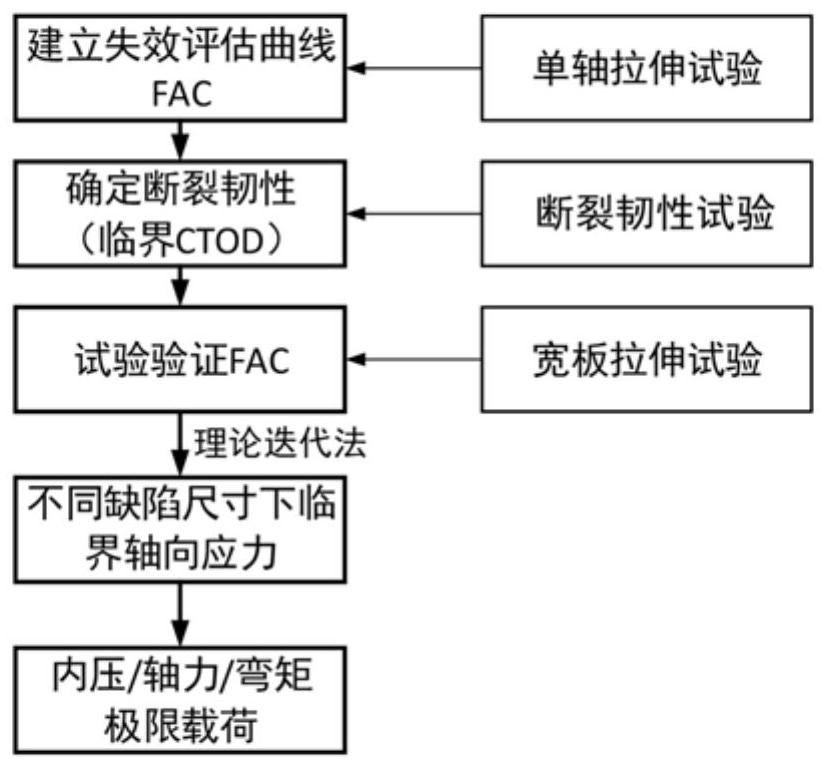
[0072] like figure 1 As shown, a method for evaluating the ultimate load of a buried pipeline with defects includes the following process:

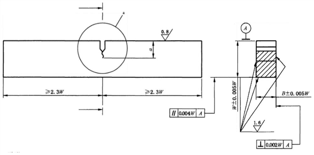
[0073] Step 1. Obtain the stress-strain curve through the uniaxial tensile test of the axial specimen of the pipeline (pipeline body and girth weld), and then obtain the yield strength σ according to the stress-strain curve y , elastic modulus E and ε ref , put σ y , E and ε ref Substituting it into the double criterion method of the failure assessment graph, the failure assessment curve of the pipeline is obtained. And the critical CTOD value of the pipeline is obtained through the unilateral notch tensile test.

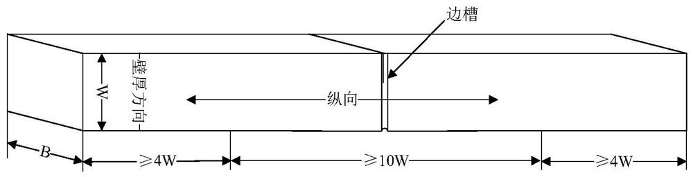
[0074] Step 2, design wide-plate tensile specimens, and conduct wide-plate tensile tests to verify the proposed failure evaluation curves.

[0075] Step 3, calculate the failure assessment point (Kr, Lr) method and verify the failure assessment curve to iteratively calculate the critical axial stress of the pipeline with d...

Embodiment 2

[0152] Create failure assessment curves

[0153] Cut the longitudinal sample of X70 material φ813mm×14.7mm pipe, and conduct longitudinal uniaxial tensile test. The tensile test engineering stress-strain curve is as follows: Figure 7 shown. Yield strength σ of X70 large deformation pipeline steel y It is 494MPa, and the tensile strength is 675MPa.

[0154] Take Lr=0.1, 0.3, 0.5, 0.7, 0.9, 0.95, 1.0, 1.05, 1.1, 1.2, then the corresponding engineering stress σ, true strain ε ref and Kr are shown in the table below;

[0155] Table 1 Failure evaluation curve solution parameter table

[0156] Lr σ ε ref

Kr 0.1 49.4 0.000235 0.997509 0.3 148.2 0.000706 0.978232 0.5 247 0.001176 0.942809 0.7 345.8 0.001647 0.896221 0.95 444.6 0.002117 0.843649 1.0 469.3 0.002235 0.830097 1.05 494 0.004352 0.686753 1.1 518.7 0.00653 0.592117 1.2 543.4 0.00878 0.529154

[0157] By fitting the curve with formula (...


PUM

PropertyMeasurementUnit
yield strengthaaaaaaaaaa
tensile strengthaaaaaaaaaa
lengthaaaaaaaaaa

Abstract

The invention discloses a method for evaluating an ultimate load borne by a buried pipeline with defects. The method comprises the following steps: step 1, performing a uniaxial tensile test on a pipeline sample, and calculating a failure evaluation curve; obtaining a critical CTOD value of the pipeline through a unilateral notch tensile test; and step 2, selecting the axial stress and defect sizeof the pipeline sample, and calculating a failure evaluation point through theoretical iterative calculation; if the failure evaluation point does not accord with the failure evaluation curve obtained in the step 1, performing recalculating until the failure evaluation points conform to the failure evaluation curve obtained in the step 1; and if the failure evaluation point conforms to the failure evaluation curve obtained in the step 1, calculating the internal pressure, bending moment and axial force limit load of the pipeline sample according to the critical axial stress and defect size. The limit value of the external load can be provided for predicting the pipeline failure behavior through the sensed pipeline load monitoring data, the pipeline safety service state is effectively mastered, and a basis is provided for pipeline safety early warning.

Description

technical field [0001] The invention belongs to the technical field of pipeline safety evaluation, in particular to a method for evaluating the limit load of buried pipelines containing defects. Background technique [0002] The safety of buried oil and gas pipelines is very important. Once damaged, the consequences will be serious. The working state of buried oil and gas pipelines is much more complicated than that of surface open-air pipelines. In addition to bearing the pressure of the working medium, they must also bear the axial force and additional bending moment caused by external loads. Weld failures that occur during pipeline operation are mostly related to external loads on the pipeline, such as mismatched trench shapes, soil movement caused by human construction activities or natural phenomena. According to the analysis of pipeline failure events, the excessive external load borne by the pipeline is one of the reasons for the failure of the girth weld. The ultim...

Claims


Application Information

Patent Timeline
Patent Type & Authority Applications(China)
IPC IPC(8): G01N3/08G01N3/20
CPCG01N3/08G01N3/20
Inventor 曹俊马卫锋王珂任俊杰聂海亮罗金恒赵新伟霍春勇
Owner BC P INC CHINA NAT PETROLEUM CORP
Why Eureka
Try Eureka