Ice melting device with reactive compensation and adjustable output current
A technology for outputting current and melting ice. It is applied in reactive power compensation, reactive power adjustment/elimination/compensation, circuit devices, etc., and can solve problems such as small current adjustment range, low applicable voltage level, and a large number of harmonics.
- Summary
- Abstract
- Description
- Claims
- Application Information
AI Technical Summary
Problems solved by technology
Method used
Image
Examples
Embodiment 1
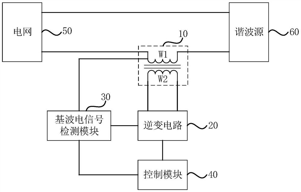
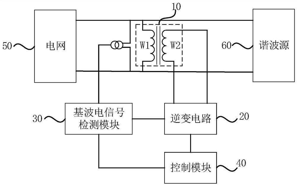
[0037] figure 1 It is a structural schematic diagram of the serial connection of the primary winding of a deicing device with reactive power compensation and adjustable output current provided in Embodiment 1 of the present invention, figure 2 It is a structural schematic diagram of parallel connection of primary windings of an ice-melting device with reactive power compensation and adjustable output current provided in Embodiment 1 of the present invention. refer to figure 1 and figure 2 , the ice-melting device includes: at least one transformer 10, at least one inverter circuit 20, a fundamental wave electric signal detection module 30 and a control module 40, wherein the transformer 10 includes a primary winding W1 and a secondary winding W2, and the primary winding W1 is connected in series or connected in parallel between the grid 50 and the harmonic source (i.e. load) 60, respectively as figure 1 As shown, the primary winding W1 is connected in series between the g...
Embodiment 2
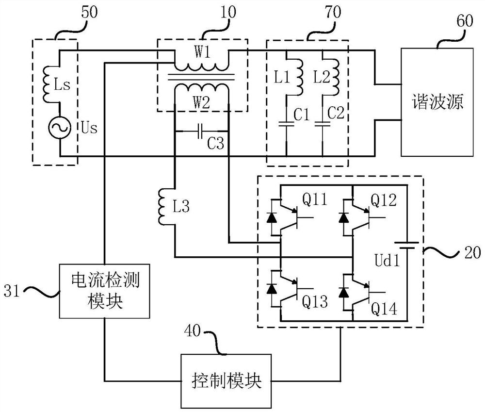
[0046] image 3 It is a schematic structural diagram of an ice-melting device with reactive power compensation and adjustable output current provided in Embodiment 2 of the present invention. On the basis of the above examples, refer to image 3 , the primary winding W1 is connected in series between the grid 50 and the harmonic source (ie load) 60, the first end of the primary winding W1 is connected to the grid 50, and the second end of the primary winding W2 is connected to the harmonic source (ie load) 60;
[0047] The ice-melting device also includes a passive filter 70, the passive filter 70 is connected in parallel between the grid 50 and the harmonic source (ie load) 60, and the first end of the passive filter 70 is connected to the second end of the primary winding W1 respectively. It is connected to the harmonic source (ie load) 60, and the second end is connected to the grid 50 and the harmonic source (ie load) 60 respectively.
[0048] Wherein, the grid 50 includ...
Embodiment 3
[0072] Figure 8 It is a structural schematic diagram of an ice-melting device with reactive power compensation and adjustable output current in Embodiment 3 of the present invention; Figure 9 It is a schematic diagram of a fundamental equivalent circuit of a parallel active filter in Embodiment 3 of the present invention; Figure 10 It is a schematic diagram of a parallel active filter harmonic equivalent circuit in Embodiment 3 of the present invention. On the basis of the above examples, refer to Figure 8 , the primary winding W1 is connected in parallel between the grid 50 and the harmonic source (ie load) 60 , the secondary winding is connected to the inverter circuit 20 , and the inverter circuit 20 is connected to the control module 40 .
[0073] Wherein, the control module 40 controls the inverter circuit 20 to generate a fundamental voltage and applies it to the secondary winding W2 side according to the fundamental voltage on the primary winding W1 side detected ...
PUM
 Abstract
Description
Claims
Application Information
 - R&D
- Intellectual Property
- Life Sciences
- Materials
- Tech Scout
- Unparalleled Data Quality
- Higher Quality Content
- 60% Fewer Hallucinations
Browse by: Latest US Patents, China's latest patents, Technical Efficacy Thesaurus, Application Domain, Technology Topic, Popular Technical Reports.
© 2025 PatSnap. All rights reserved.Legal|Privacy policy|Modern Slavery Act Transparency Statement|Sitemap|About US| Contact US: help@patsnap.com


