
Hybrid new energy power generation device

A power generation device and new energy technology, applied in the direction of circuit devices, battery circuit devices, photovoltaic power generation, etc., can solve the problems of limited light concentrating effect, single power generation equipment, low efficiency, etc., to achieve regular cleaning, good lighting angle, and convenient The effect of disassembly

Inactive Publication Date: 2021-03-19
苏州碳索能源科技有限公司
View PDF10 Cites 0 Cited by
  • Summary
  • Abstract
  • Description
  • Claims
  • Application Information

AI Technical Summary

Problems solved by technology

The existing common solar panels are flat and cannot automatically adjust the angle with the change of the illumination angle. The flat solar panel absorbs solar energy and directly converts it into electrical energy and stores it. However, the concentrating effect of the flat solar panel is limited, and it is difficult to Sufficiently receive sunlight, resulting in low power generation efficiency of solar panels
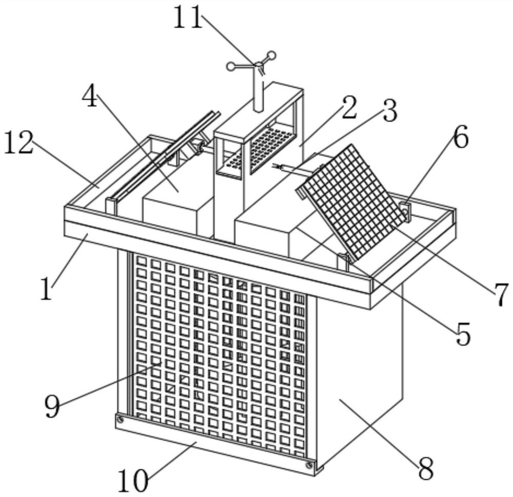
[0004] In the prior art, the power generation equipment is relatively single, generally only wind energy, solar energy, tidal energy independent power generation equipment, its power generation effect is average, the efficiency is low, it is difficult to make full use of natural resources for power generation, therefore, the inventor proposes a hybrid The new energy power generation device can combine tidal energy and solar energy to generate electricity, and its efficiency is greatly improved

Method used


Image

  • Hybrid new energy power generation device
  • Hybrid new energy power generation device
  • Hybrid new energy power generation device

Examples


Embodiment Construction

[0029] In order to make the technical means, creative features, goals and effects achieved by the present invention easy to understand, the present invention will be further described below in conjunction with specific embodiments.

[0030] In the description of the present invention, it should be noted that the terms "upper", "lower", "inner", "outer", "front end", "rear end", "both ends", "one end", "another end" The orientation or positional relationship indicated by etc. is based on the orientation or positional relationship shown in the drawings, and is only for the convenience of describing the present invention and simplifying the description, rather than indicating or implying that the referred device or element must have a specific orientation, use a specific Azimuth configuration and operation, therefore, should not be construed as limiting the invention. In addition, the terms "first" and "second" are used for descriptive purposes only, and should not be understood ...


PUM


Abstract

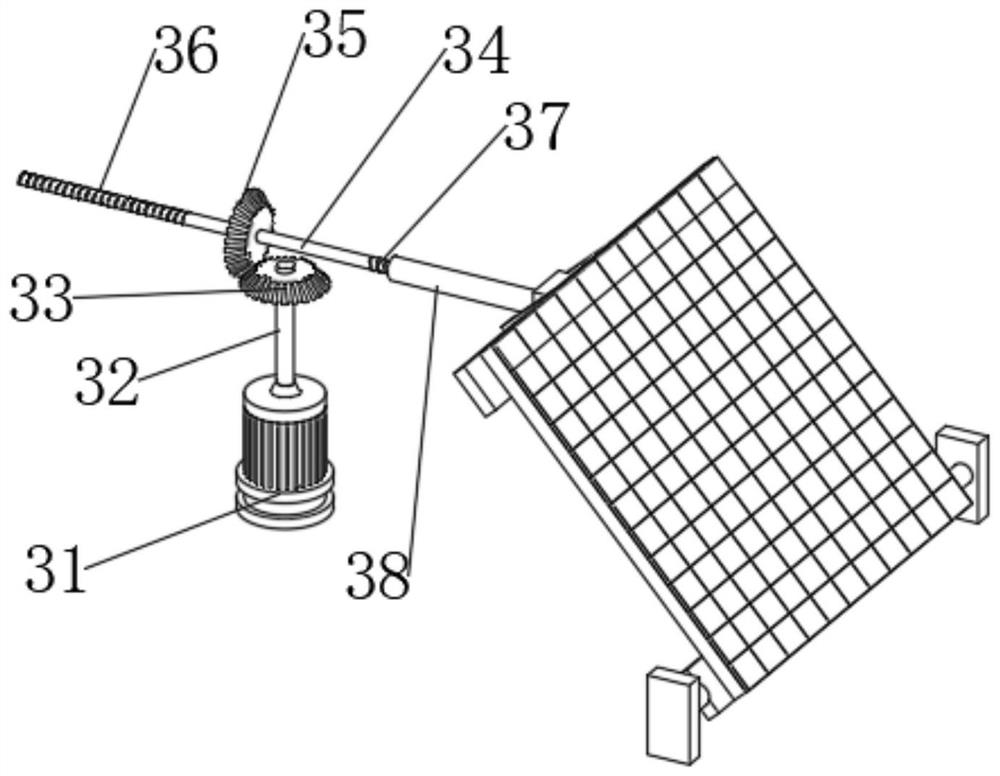
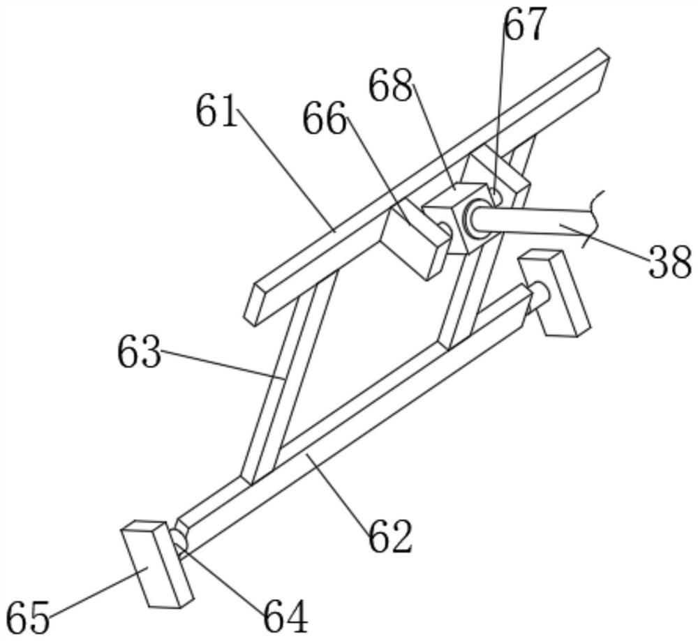
The invention discloses a hybrid new energy power generation device. The device comprises a floating plate, wherein baffles are fixedly installed on the periphery of the upper end face of the floatingplate, a working box is fixedly installed in the middle of the upper end of the floating plate, a storage battery and a control box are fixedly installed in the middle of the upper end of the floating plate, and a driving mechanism is arranged in the working box; mounting assemblies and solar panels are arranged on the left portion and the right portion of the upper end of the floating plate correspondingly, vertical plates are fixedly mounted on the left portion and the right portion of the lower end of the floating plate correspondingly, a hydroelectric generation assembly is arranged between the two vertical plates, and partition nets are fixedly mounted on the front portions and the rear portions of the opposite faces of the two vertical plates correspondingly; fixing pieces are arranged at the lower ends of the separation nets, and a bird repelling device is fixedly installed in the middle of the upper end of the work box. According to the hybrid new energy power generation device, hydroelectric generation and solar power generation are perfectly integrated, the utilization rate of natural resources can be effectively increased, and the hybrid new energy power generation device is wide in application range and high in benefit.

Description

technical field [0001] The invention relates to the technical field of new energy power generation, in particular to a hybrid new energy power generation device. Background technique [0002] In response to global warming caused by the greenhouse effect and the impact of global warming, environmental awareness is gradually rising, and countries are also starting to sign relevant environmental protection conventions to curb carbon dioxide emissions, so the development of alternative energy that can replace traditional fossil fuels It has become a focus of active research by countries all over the world. Since solar energy and wind energy are inexhaustible, clean and pollution-free new energy sources, new energy sources have both the advantages of economy and environmental protection. New energy refers to various energy forms other than traditional energy. At present, the technology is relatively mature, and the new energy that has begun to be used on a large scale is wind ene...

Claims


Application Information

Patent Timeline
IPC IPC(8): H02S20/30H02J7/35F03B13/00B01D29/01B01D29/96
CPCB01D29/01B01D29/96F03B13/00F05B2220/706H02J7/35H02S20/30Y02E10/50
Inventor 卓法
Owner 苏州碳索能源科技有限公司
Learn More