Pneumatic tire

A pneumatic tire, tire circumferential technology, applied in road vehicle tires, tire parts, tire tread/tread pattern, etc., can solve the problem of insufficient braking performance, and achieve the goal of suppressing poor appearance and improving braking performance, the effect of reducing appearance defects

Active Publication Date: 2021-03-19
THE YOKOHAMA RUBBER CO LTD
View PDF12 Cites 0 Cited by
  • Summary
  • Abstract
  • Description
  • Claims
  • Application Information

AI Technical Summary

Problems solved by technology

[0003] However, reducing the number of sipes and shortening the length in the tire width direction not only changes the appearance of the tire, but also has the problem that the braking performance on wet or snowy roads due to the sipe cannot be sufficiently obtained.

Method used


Image

  • Pneumatic tire
  • Pneumatic tire
  • Pneumatic tire

Examples


Embodiment

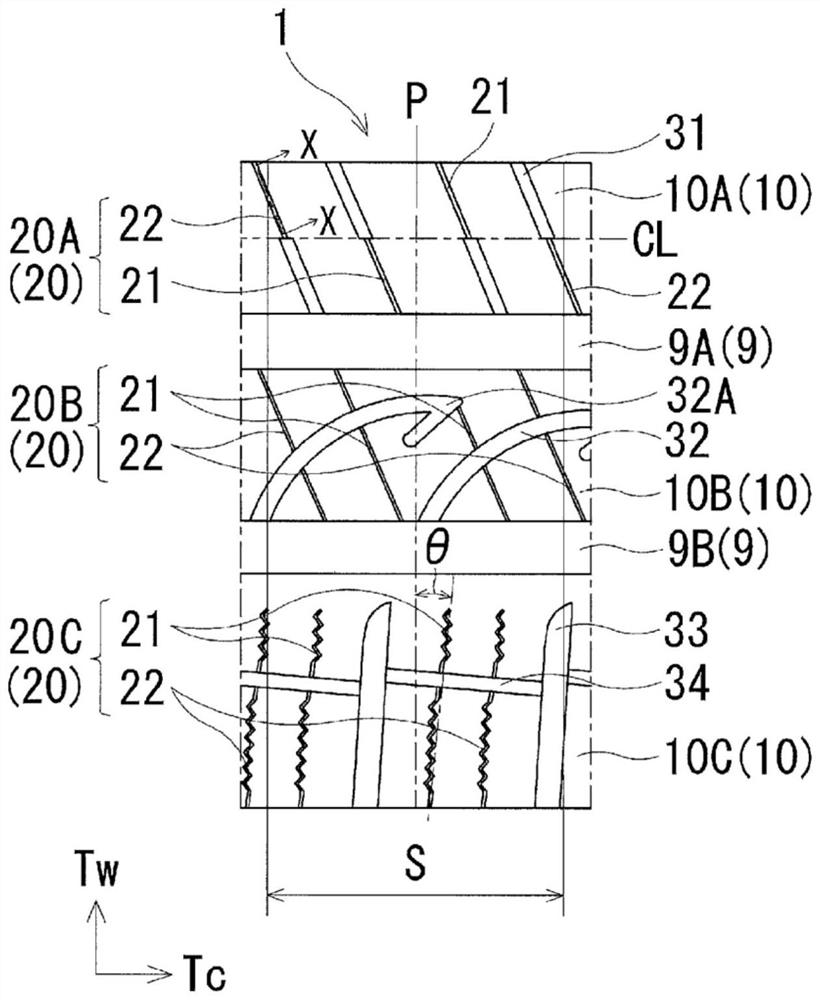
[0042] Tires of Conventional Example, Comparative Example, and Examples 1 to 7 were produced. These tires had a tire size of 205 / 55R16 and were provided with: a plurality of circumferential grooves extending in the tire circumferential direction in the tread portion; These circumferential grooves define; and a plurality of sipes extending in the tire width direction in at least one row of land portions, the tread portion being formed of a plurality of sectors divided in the tire circumferential direction, in the pneumatic tire, as shown in Table 1 Set the following: the presence or absence of sipe in the boundary area, the presence or absence of shallow bottom sipe, the range of the boundary area, the bottom elevation ratio of shallow bottom sipe, and the shallow bottom in each land portion. Comparison of the number of sipe lines, the inclination angle θ of the sipe in the center land portion, the inclination angle θ of the sipe in the middle land portion, and the inclination a...


PUM


Abstract

Provided is a pneumatic tire for which it is possible to improve braking performance on a wet road surface and a snowy road surface without changing the appearance of the tire and reduce the possibility of the appearance being degraded. The tread portion 1 of this pneumatic tire has: a plurality of circumferential grooves 9 that extend in the tire circumferential direction; a plurality of rows ofland portions 10 that are partitioned by the circumferential grooves 9; and a plurality of sipes 20 that extend in the tire width direction in at least one row of the land portions 10. The tread portion 1 is molded by a plurality of sectors which are divided in the tire circumferential direction. The sipes 20 include: at least one shallow sipe 21 that is disposed in a boundary region S including the sector division position P; and a plurality of normal sipes 22 that are arranged at positions further away from the sector division position P than the shallow sipe 21. The shallow sipe 21 is madeshallower than the normal sipes 22.

Description

technical field [0001] The present invention relates to a pneumatic tire, and more specifically, provides a pneumatic tire capable of improving braking performance on wet roads and snowy roads and reducing appearance defects without changing the appearance of the tire. Background technique [0002] When vulcanizing and molding a pneumatic tire having a plurality of sipes in the tread portion, there is a problem that the tire mold and the tread rubber adhere to each other, resulting in poor appearance of the vulcanized pneumatic tire. Such bonding between the tire mold and the tread rubber is remarkable in winter tires in which many sipes are arranged on the tread portion. On the other hand, it has been proposed to reduce the number of sipes in the boundary region including the division position of the segment and to shorten the length of the sipe in the tire width direction (for example, refer to Patent Documents 1 and 2). [0003] However, reducing the number of sipes and ...

Claims


Application Information

Patent Timeline
Patent Type & Authority Applications(China)
IPC IPC(8): B60C11/12
CPCB60C11/0306B60C2011/0381B60C2011/1209B60C2011/1213B60C11/1263B60C2011/1268B60C2011/036B60C2011/0365B60C2011/0372B60C2011/0341B60C11/04B60C11/1204B60C2200/04B60C2011/1227B60C11/1236B60C11/12B60C11/1259
Inventor 长安政明
Owner THE YOKOHAMA RUBBER CO LTD
Why Eureka
Try Eureka