Emergency showering fire extinguishing device for laboratory
A technology for laboratory and fire extinguishing devices, which is applied in the direction of fire alarms, applications, and household heating that rely on smoke/gas effects to achieve the effects of improving efficiency, improving safety, and improving filtering effects
- Summary
- Abstract
- Description
- Claims
- Application Information
AI Technical Summary
Problems solved by technology
Method used
Image

Examples
Embodiment 1
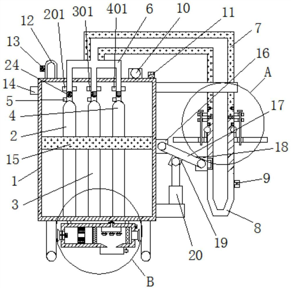
[0031] Such as Figure 1-Figure 5As shown, the present invention provides a laboratory emergency shower fire extinguishing device, comprising a box body 1, the inside of the box body 1 is respectively provided with a No. 1 storage tank 2, a No. 2 storage tank 3 and a No. 3 storage tank 4; No. 2 storage tank 2, No. 2 storage tank 3 and No. 3 storage tank 4 are provided with No. 1 control valve 201, No. 2 control valve 301 and No. 3 control valve 401 at the output ends of No. 1 storage tank 2 and No. 2 storage tank 3 The output end of No. 3 storage tank 4 is connected with a three-way pipe 6; the top of the three-way pipe 6 is connected with a connecting pipe 7, and one end of the connecting pipe 7 is provided with a nozzle 8; one side of the nozzle 8 is provided with a temperature The remote sensor 9 is fixedly connected with a protective plate 15 on the inner wall of the box body 1; the No. 1 storage tank 2, the No. There is a No. 1 connection block 16 fixedly connected; the ...
Embodiment 2
[0037] Such as figure 1 , 4 As shown, the difference between this embodiment and the foregoing embodiment is that;
[0038] The bottom end of casing 1 is provided with purifying device 21, and the inside of purifying device 21 is respectively provided with No. 1 cavity 2101 and No. 2 cavity 2102, and the top of purifying device 21 is provided with water pump 2103; The top of the cavity 2102 is connected, and the inside of the second cavity 2102 is respectively provided with a spray head 2104, a filter plate 2105 and an activated carbon adsorption plate 2106; the inside of the second cavity 2102 is respectively provided with a motor 2108 and a fan 2109, and The output end of 2108 is fixedly connected with the fan 2109, and the bottom end of the purification device 21 is provided with a water storage tank 23;
[0039] Such as Figure 4 As shown, in one of the preferred technical solutions of this embodiment, a barrier plate 2107 is fixedly connected between the first cavity 2...
Embodiment 3
[0042] Such as figure 2 As shown, the difference between this embodiment and the foregoing embodiment is that;
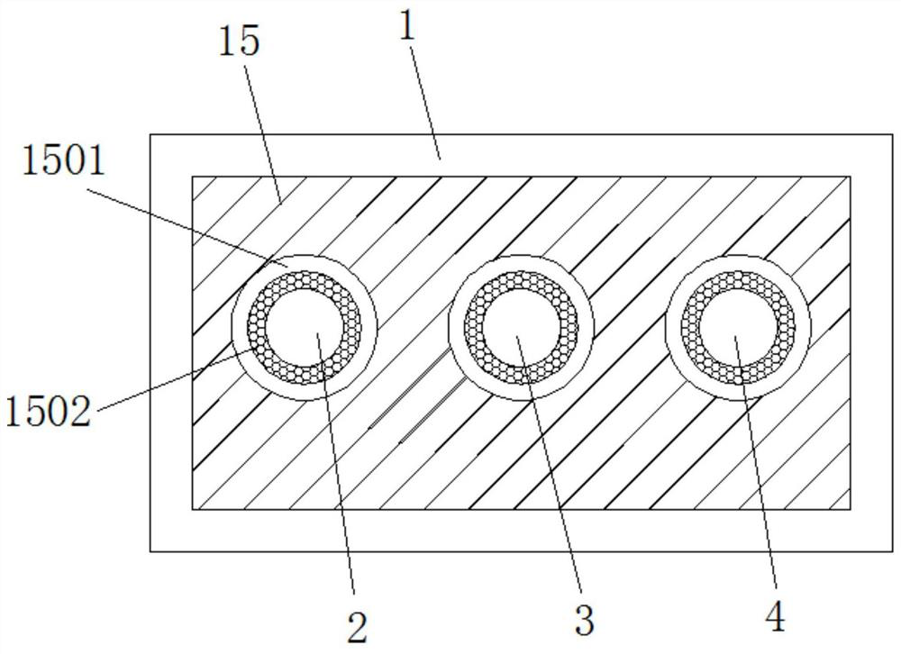
[0043] The inside of the protective plate 15 is provided with a number of limit holes 1501, and the inside of the limit holes 1501 are respectively connected with the No. 1 storage tank 2, the No. 2 storage tank 3 and the No. 3 storage tank 4; Protective pads 1502 are provided, and the protective pads 1502 are attached to the outer walls of the No. 1 storage tank 2 , the No. 2 storage tank 3 and the No. 3 storage tank 4 respectively.
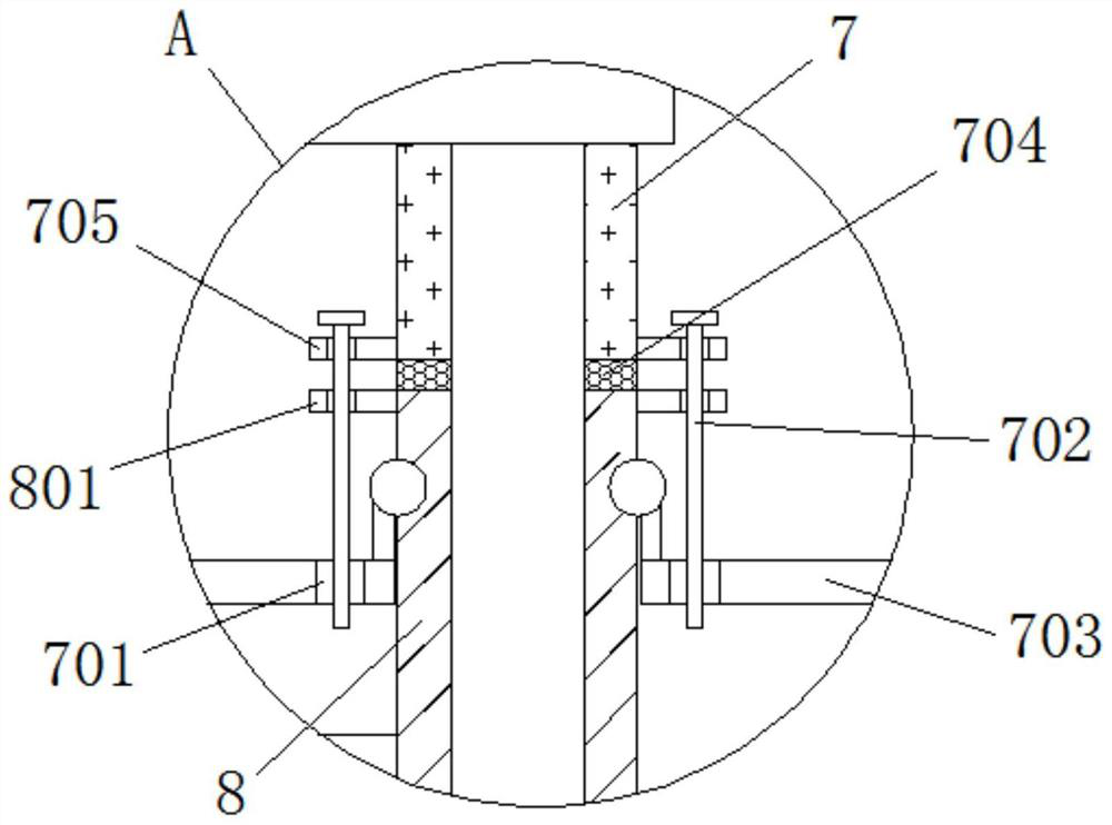
[0044] Such as figure 1 , 3 As shown, in one of the preferred technical solutions of this embodiment, the nozzle 8 communicates with the connecting pipe 7; the connecting pipe 7 and the left and right sides of the nozzle 8 are respectively fixedly connected to the No. 1 fixing plate 705 and the No. 2 fixing plate 801 A gasket 704 is provided at the connection between the connecting pipe 7 and the spray head 8 .
[0045] Such as ...
PUM
 Abstract
Description
Claims
Application Information
 - R&D
- Intellectual Property
- Life Sciences
- Materials
- Tech Scout
- Unparalleled Data Quality
- Higher Quality Content
- 60% Fewer Hallucinations
Browse by: Latest US Patents, China's latest patents, Technical Efficacy Thesaurus, Application Domain, Technology Topic, Popular Technical Reports.
© 2025 PatSnap. All rights reserved.Legal|Privacy policy|Modern Slavery Act Transparency Statement|Sitemap|About US| Contact US: help@patsnap.com