Well control project monitoring system

An engineering monitoring and circulation system technology, which is applied to the automatic control system of drilling, measurement, drilling equipment, etc., can solve the problems of dangerous well control, blowout out of control, low precision, etc., to prevent diffusion, prevent falling objects, and reduce labor intensity effect

Inactive Publication Date: 2014-09-17
PANJIN CHUNYA PETROLEUM TECH
View PDF10 Cites 10 Cited by
  • Summary
  • Abstract
  • Description
  • Claims
  • Application Information

AI Technical Summary

Problems solved by technology

This method has the following disadvantages: 1. The influence of the volume of the mud tank: (the surface area of ​​the mud tank is large, and the small change in the liquid level involves a large amount of mud); 2. The influence of the accuracy of the ultrasonic liquid level sensor: (installation position, inclination, liquid level fluctuation, Large errors caused by temperature, steam, tank vibration, etc.); 3. The impact of engineering construction: (mixing mud, water and medicine, disturbance of the mixer, desanding and loss of mud, running mud, etc. lead to inaccurate measurement); 4. Export target type Low flow measurement accuracy: (conduit inclination angle, mud density, target length, temperature, vibration, etc. lead to low accuracy); Water efficiency, cylinder liner size, etc. lead to large errors in measuring relative flow rates)
Many of the above factors lead to inaccurate monitoring of well control engineering
[0004] Therefore, in the monitoring method of well control engineering, many disadvantages lead to vicious accidents such as well control danger and out-of-control blowout (such as the out-of-control blowout explosion and fire accident in the US Gulf of Mexico drilling in 2010)
In particular, the risk of well control on offshore drilling platforms is extremely high, and once the control is lost, the consequences will be disastrous

Method used


Image

  • Well control project monitoring system
  • Well control project monitoring system

Examples


Embodiment Construction

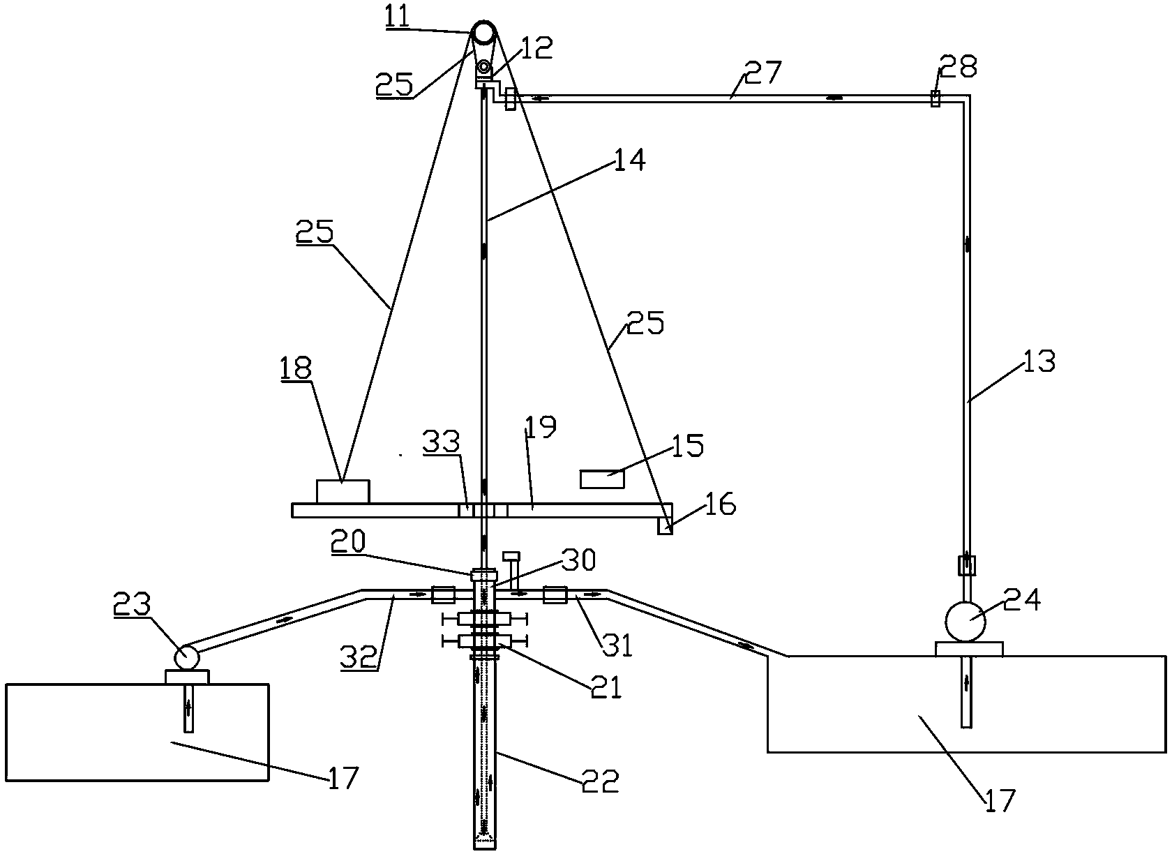
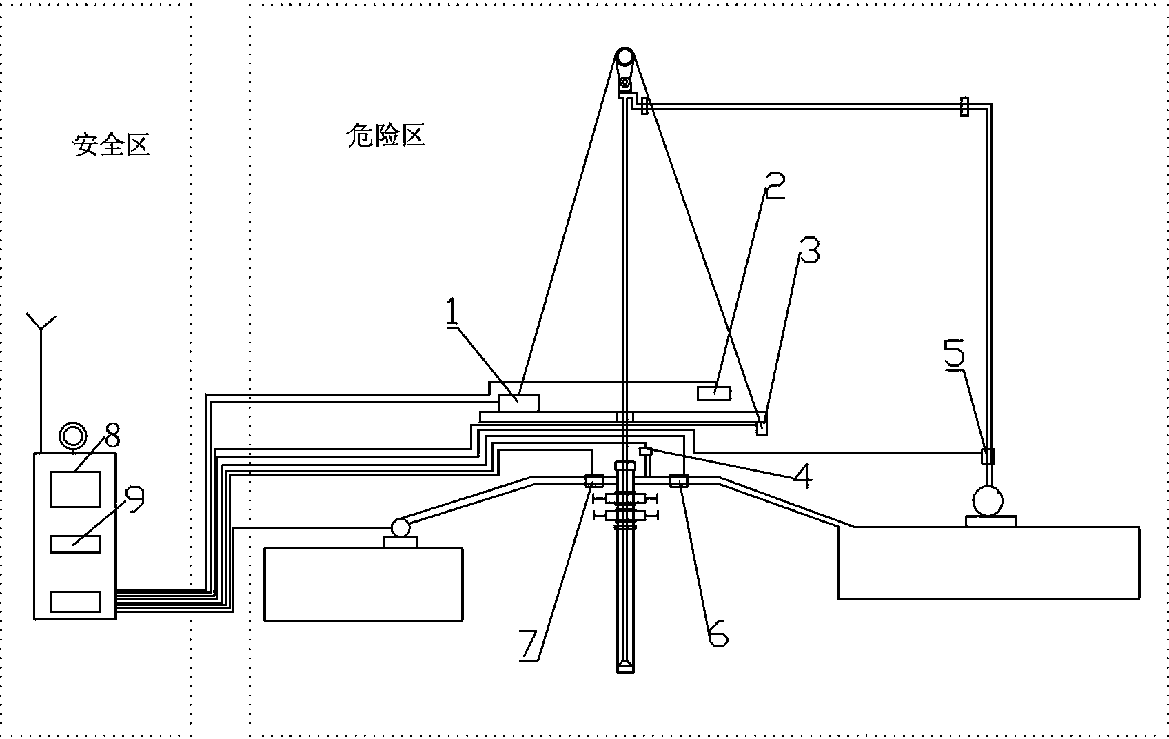
[0023] Such as figure 1 and figure 2 As shown, a well control engineering monitoring system includes a drill floor adjustment device. The drilling tool 14 is inserted into the wellbore 22 through the drill floor adjustment device. Circulation, connecting the overflow prevention pipe 30 above the wellbore 22, the upper end of the overflow prevention pipe 30 is provided with a wellhead sealer 20, and the lower part of the overflow prevention pipe is provided with a blowout preventer 21, between the wellhead sealer 20 and the blowout preventer 21 After passing through the grouting pipe 32 and the grouting pump 23 in sequence, it is connected with the mud tank 17. The grouting pipe 32 is provided with a grouting pipe flow sensor 7, and the grouting pipe flow sensor 7 is used to monitor the flow of grouting in the grouting pipe 32 to the wellbore 22; At the conduit of the outlet of the overflow prevention pipe 30 in the mud circulation system, a conduit flow sensor 6 is provided,...


PUM


Abstract

The invention relates to a well control project monitoring system comprising a drill floor adjusting device, a drilling tool is inserted into a borehole through the drill floor adjusting device, a sludge circulation system passes through an inner cavity of the drilling tool, circulates in the annular space of the borehole out of a circulation tank and then is pumped into the inner cavity of the drilling tool through a sludge pump to form a closed loop, an anti-spilling pipe is connected to the upper portion of the borehole, the upper end of the anti-spilling pipe is provided with a wellhead sealer, a blowout preventer is arranged at the lower portion of the anti-spilling pipe, a grout pipe and a grout pump sequentially pass through the position between the wellhead sealer and the blowout preventer and then are connected with a sludge tank, the grout pipe is provided with a grout pipe flow sensor, a guide pipe flow sensor is arranged at the position, at a guide pipe of an outlet of the anti-spilling pipe, of the sludge circulation system, and a vertical pipe flow sensor is arranged at an inlet of the sludge circulation system. The well control project monitoring system is stable in performance, can achieve recording and wireless remote transmission of on-the-spot working information in real time, and provides the basis for integration of the spot and a foundation, information sharing, remote control commanding, accident replaying and investigation treatment.

Description

technical field [0001] The invention relates to a well control engineering monitoring system, which is suitable for real-time online monitoring of well control engineering in the construction process of various oil drilling and major workover operations, and is especially suitable for offshore drilling, ultra-deep wells, exploration wells, and "three high" oil and gas Real-time monitoring of well control engineering in well operation and construction. Background technique [0002] With the continuous improvement of drilling technology and the implementation of new technology, the depth of drilling increases, and the complexity and difficulty of formations encountered in drilling become more and more complex; once a blowout occurs out of control during drilling, it will cause huge catastrophic losses. It often causes equipment damage, casualties, oil and gas well scrapping, environmental pollution and adverse social impact; while the well control engineering monitoring techno...

Claims


Application Information

Patent Timeline
Patent Type & Authority Applications(China)
IPC IPC(8): E21B47/00E21B47/10E21B21/08E21B44/00
Inventor 许广奎赵家敏王铁晨任洪生刘宝学李永亮尚久红吴淑萍高雅静丛玉丽许珊珊文舜智孙小迪任会来李璐刘传义沈磊赵明明
Owner PANJIN CHUNYA PETROLEUM TECH
Why Eureka
Try Eureka