Eureka AIR delivers breakthrough ideas for toughest innovation challenges, trusted by R&D personnel around the world.

Coding colored tape coating machine

A coating machine and color coding technology, applied in the field of coating machines, can solve the problems of affecting the coating quality and the inability to apply the coating evenly, so as to achieve the effect of improving the quality

Inactive Publication Date: 2021-03-23
XINXIANG XINBEIR INFORMATION MATERIAL
View PDF6 Cites 0 Cited by
  • Summary
  • Abstract
  • Description
  • Claims
  • Application Information

AI Technical Summary

Problems solved by technology

[0005] Based on the above problems, the object of the present invention is to provide a coding ribbon coater, which is used to solve the problem that the coater in the prior art cannot evenly coat the coating on the outer surface, thereby affecting the coating quality.

Method used

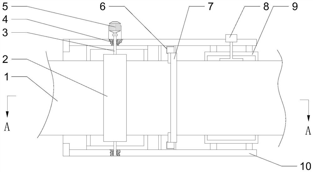

Image

  • Coding colored tape coating machine
  • Coding colored tape coating machine
  • Coding colored tape coating machine

Examples


Embodiment 1

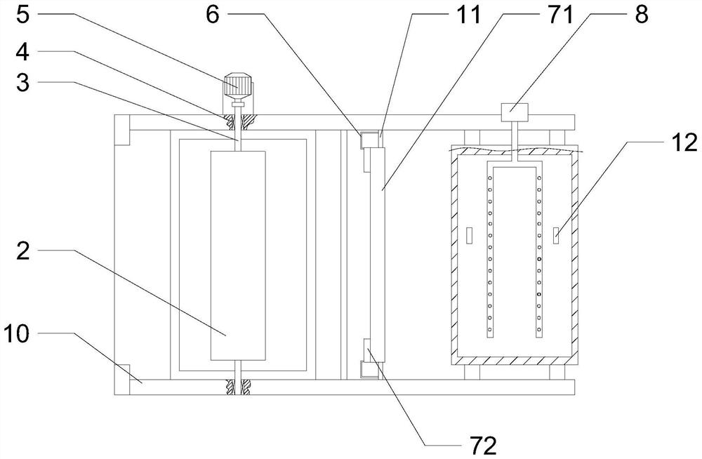
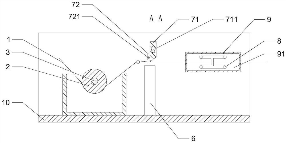
[0028] Such as Figure 1-5 As shown, a coding ribbon coating machine includes a frame 10, a first rotating shaft 3 is installed through a bearing 4 on the frame 10, a coating roller 2 is installed on the first rotating shaft 3, and one end of the first rotating shaft 3 is installed There is a power mechanism, and a second rotating shaft 11 is also installed on the frame 10, and a smoothing mechanism 7 is installed on the second rotating shaft 11 along its length direction, and the smoothing mechanism 7 includes a smoothing block 72 formed into one with each other and two outlets. Material block 71, two discharge blocks 71 are positioned at the both sides of plastering block 72, discharge port 711 is arranged on the discharge block 71, and the material receiving box 6 that is positioned at the discharge port 711 below is installed on the frame 10, the first The two rotating shafts 11 pass through the smoothing block 72 .

[0029] Working principle: When coating 1 needs to be c...

Embodiment 2

[0032] Such as Figure 1-5 Shown, on the basis of above-mentioned embodiment 1, present embodiment provides the preferred structure that coating 1 can be dried, and promptly is positioned at the rear of smoothing mechanism 7 on frame 10 and is also equipped with drying mechanism, and drying mechanism includes installation In the drying box 9 on the frame 10, a drying cavity 91 is arranged in the drying box 9, a feeding nozzle is arranged at the front portion of the drying box 9, and a discharge nozzle is arranged at the rear portion, and a device extending to the drying cavity is installed on the frame 10. Air-drying assembly 8 in 91; Air-drying assembly 8 comprises the fan 83 that is installed on the frame 10, and the main air duct 82 that extends in the drying chamber 91 is installed on the fan 83, is connected with vertical pipe 87 on the main air duct 82, The upper end of the vertical pipe 87 is connected with the upper air duct unit, and the lower end is connected with th...


PUM


Abstract

The invention relates to the technical field of coating machines, in particular to a coding colored tape coating machine, which is used for solving the problem that in the prior art, a coating machinecannot uniformly coat paint on the outer coating surface, and consequently the coating quality is affected. The coding colored tape coating machine comprises a rack, a first rotating shaft and a coating roller; a power mechanism is installed at one end of the first rotating shaft; a second rotating shaft is further installed on the rack; a trowelling mechanism is installed on the second rotatingshaft in the length direction of the second rotating shaft, and the trowelling mechanism comprises a trowelling block and two discharging blocks which are integrally formed; the two discharging blocksare located on the two sides of the trowelling block; discharging openings are formed in the discharging blocks; a material receiving box located below the discharging openings is installed on the rack; and the second rotating shaft penetrates through the trowelling block. According to the coding colored tape coating machine provided by the invention, after the coating roller is used for coatingthe outer surface of a coating, the coating passes through the lower part of the trowelling block and is in contact with the trowelling block, and the coating on the outer surface of the coating can be coated more uniformly through the trowelling block, so that the coating quality can be improved.

Description

technical field [0001] The invention relates to the technical field of coating machines, and more specifically relates to a coding ribbon coating machine. Background technique [0002] The coating machine is mainly used for the surface coating process production of film, paper, etc. This machine is to coat the rolled substrate with a layer of glue, paint or ink with specific functions, and then wind it up after drying. It uses a special The multi-functional coating head can realize various forms of surface coating production. The winding and unwinding of the coating machine is equipped with a full-speed automatic film splicing mechanism, and the PLC program tension closed-loop automatic control. [0003] The coating machine in the prior art includes a coating machine main body and a control panel support column. The bottom end of the coating machine main body is provided with a coating machine fixed base, and the inner side of the coating machine fixed base is provided with ...

Claims


Application Information

Patent Timeline
Patent Type & Authority Applications(China)
IPC IPC(8): B05C1/12B05C9/14B05C11/02B05D3/04
CPCB05C1/12B05C9/14B05C11/023B05D3/0406B05D3/0413
Inventor 赵建设
Owner XINXIANG XINBEIR INFORMATION MATERIAL
Why Eureka
Eureka Blog
Learn More