
Drilling equipment for clutch production

A technology of drilling equipment and clutch, which is applied in drilling/drilling equipment, boring/drilling, metal processing equipment, etc. It can solve the problems of debris handling that needs to be improved, and the clutch plate cannot be cleaned, so as to improve the practicality , avoid plugging holes, and ensure smoothness

Active Publication Date: 2022-02-11
日照市七星汽车部件股份有限公司
View PDF7 Cites 0 Cited by
  • Summary
  • Abstract
  • Description
  • Claims
  • Application Information

AI Technical Summary

Problems solved by technology

The drilling equipment in the above-mentioned patent has the following disadvantages: although it can meet certain drilling requirements, it cannot clean the clutch plate at the same time, and the treatment of debris during drilling needs to be improved

Method used


Image

  • Drilling equipment for clutch production
  • Drilling equipment for clutch production
  • Drilling equipment for clutch production

Examples


Embodiment Construction

[0028] The technical solution of this patent will be further described in detail below in conjunction with specific embodiments.

[0029] Embodiments of the present patent are described in detail below, examples of which are shown in the drawings, wherein the same or similar reference numerals designate the same or similar elements or elements having the same or similar functions throughout. The embodiments described below by referring to the figures are exemplary and are only used for explaining the patent, and should not be construed as limiting the patent.

[0030] In the description of this patent, it is to be understood that the terms "center", "upper", "lower", "front", "rear", "left", "right", "vertical", "horizontal", The orientation or positional relationship indicated by "top", "bottom", "inner", "outer", etc. is based on the orientation or positional relationship shown in the drawings, and is only for the convenience of describing this patent and simplifying the des...


PUM


Abstract

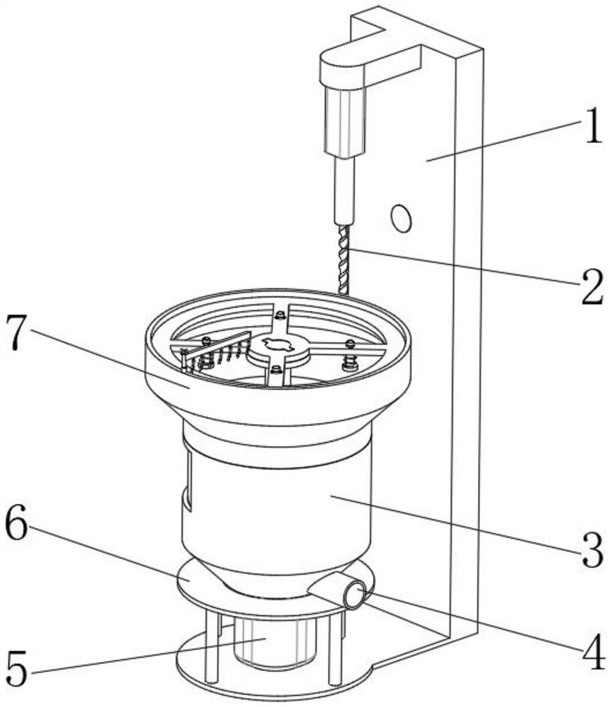
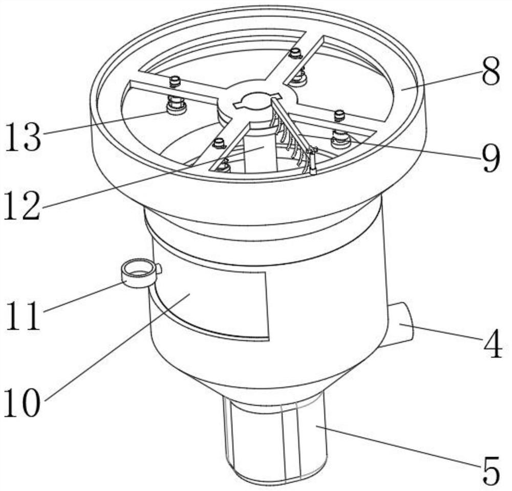
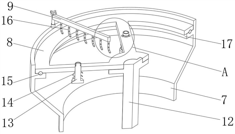
The invention discloses a drilling equipment for clutch production, which relates to the technical field of clutch drilling equipment; in order to facilitate the cleaning of clutch discs while drilling; it specifically includes a mounting frame, and a drilling hole is installed on the outer wall of one side of the mounting frame The outer wall of one side of the installation frame is equipped with a separation chamber through the support frame, the outer wall of the top of the separation chamber is welded with a bearing platform, the outer wall of one side of the installation frame is installed with a motor through a motor seat, and the output end of the motor is connected through a coupling There is a rotating main shaft; the top side wall of the rotating main shaft is fixed with a supporting frame carrying a clutch disc through screws. In the present invention, by setting the drilling mechanism, the motor and the rotating main shaft, the clutch plate can be rotated to complete the drilling work in multiple places, and by setting the support frame, the drip frame and the first brush head, the clutch plate can be rotated while the support frame carries the clutch plate. , using the drip rack and the first brush head to brush the surface of the clutch plate.

Description

technical field [0001] The invention relates to the technical field of clutch drilling equipment, in particular to a drilling equipment for clutch production. Background technique [0002] The clutch is a common part in mechanical transmission, which can separate or engage the transmission system at any time; in the production and processing of the clutch, it needs to be drilled for subsequent assembly. Although the current general drilling equipment can meet certain requirements However, the debris generated during the drilling process is often scattered on the surface of the clutch, which not only has poor environmental protection, but even affects production to a certain extent. [0003] After retrieval, the Chinese patent application number is CN201920852355.1, which discloses a drilling equipment for clutch face processing, which involves the technical field of auto parts processing, including feeding devices, operating frames, drilling parts, and the first air inlet pi...

Claims


Application Information

Patent Timeline
Patent Type & Authority Patents(China)
IPC IPC(8): B23B41/00B23B47/20B23Q3/06B23Q11/00B23Q11/08
CPCB23B41/00B23Q5/28B23Q3/06B23Q11/0042B23Q11/08
Inventor 雷发林陈修山徐英杰胡田
Owner 日照市七星汽车部件股份有限公司
Learn More