Blade surface smoothing and cleaning equipment of hydroelectric generator

A generator blade and smooth surface technology, which is applied in the direction of grinding/polishing equipment, metal processing equipment, grinding machine tool parts, etc., can solve the problems of difficult operation, difficult manual grinding, poor grinding effect, etc., and achieve improved firmness performance, improved practicability and reliability, and the effect of improving practicability

Active Publication Date: 2021-03-23
湖南中加国际水电有限公司
View PDF8 Cites 1 Cited by
  • Summary
  • Abstract
  • Description
  • Claims
  • Application Information

AI Technical Summary

Problems solved by technology

[0002] As we all know, a hydroelectric generator is a new energy acquisition device that mainly uses the power of water flow to drive the blades on it to rotate, thereby driving the generator to run and generate electricity. The generator mainly relies on the blades on it to provide power, and the shape of the blades is usually twisted. The curved shape of the blade can accept the impact force of the water flow on a large area. The surface of the existing blade needs to be polished during production, so as to make the surface of the blade smooth and remove impurities such as burrs remaining on it, which is convenient for water It flows on the blades, and the grinding of the blades is mainly done manually by workers relying on the grinder, and then because the shape of the blades is usually a twisted arc, its shape is irregular, it is difficult to manually grind, it is not easy to operate, and the grinding takes a long time , the work efficiency is low, and the uniformity of manual grinding is poor, resulting in low smoothness of the blade surface and poor grinding effect

Method used


Image

  • Blade surface smoothing and cleaning equipment of hydroelectric generator
  • Blade surface smoothing and cleaning equipment of hydroelectric generator
  • Blade surface smoothing and cleaning equipment of hydroelectric generator

Examples


Embodiment Construction

[0020] The specific implementation manners of the present invention will be further described in detail below in conjunction with the accompanying drawings and embodiments. The following examples are used to illustrate the present invention, but are not intended to limit the scope of the present invention.

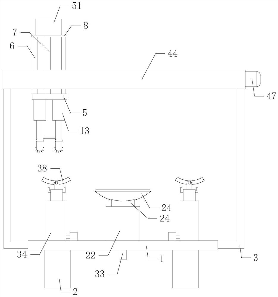
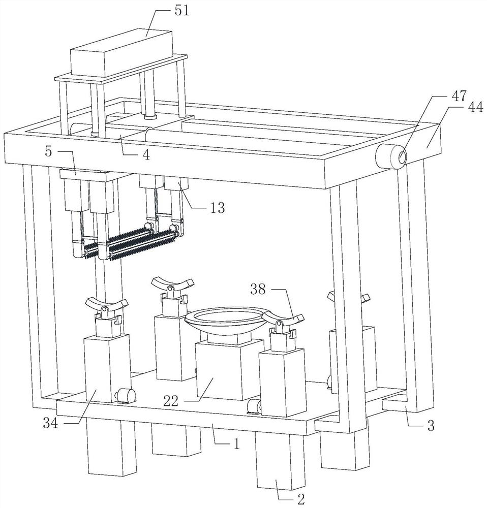
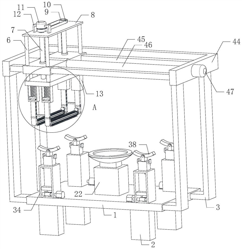
[0021] Such as Figure 1 to Figure 6 As shown, the surface smooth cleaning equipment of the hydraulic generator blade of the present invention, when it is working, the blade of the hydraulic generator is placed on the fixing device, and the fixing device fixes it, and the tops of the four groups of lifting devices are all connected to the bottom of the blade. Outer contact, four sets of lifting devices can lift the blades, thereby preventing the blades from moving randomly, the fixed direction of the blades corresponds to the direction of the two sets of brush rollers 19, and the two sets of second motors 20 are turned on, and the two sets of second motors 20 pass through ...


PUM


Abstract

The invention relates to the technical field of mechanical equipment, in particular to blade surface smoothing and cleaning equipment of a hydroelectric generator. According to the blade surface smoothing and cleaning equipment, a blade of the hydroelectric generator is automatically polished, so that physical strength and time during manual polishing can be effectively saved, the blade polishingdifficulty is reduced, the working efficiency is improved, meanwhile, the blade polishing uniformity is improved, the surface smoothness of the blade is effectively improved, the polishing effect is improved, and the practicability and reliability are improved. The equipment comprises a workbench, four sets of support legs, four sets of first support frames, a first moving plate, a second moving plate, four sets of guide rods, two sets of first screws and a mounting plate, wherein the four sets of support legs are uniformly installed at the bottom of the workbench; the four sets of first support frames are installed at the left side and the right side of the workbench separately; a fixing device is arranged in the middle of the top end of the workbench; and four sets of lifting devices arearranged on the periphery of the outer side of the fixing device.

Description

technical field [0001] The invention relates to the technical field of mechanical equipment, in particular to equipment for cleaning the smooth surface of blades of hydraulic generators. Background technique [0002] As we all know, a hydroelectric generator is a new energy acquisition device that mainly uses the power of water flow to drive the blades on it to rotate, thereby driving the generator to run and generate electricity. The generator mainly relies on the blades on it to provide power, and the shape of the blades is usually twisted. The curved shape of the blade can accept the impact force of the water flow on a large area. The surface of the existing blade needs to be polished during production, so as to make the surface of the blade smooth and remove impurities such as burrs remaining on it, which is convenient for water It flows on the blades, and the grinding of the blades is mainly done manually by workers relying on the grinder, and then because the shape of ...

Claims


Application Information

Patent Timeline
Patent Type & Authority Applications(China)
IPC IPC(8): B24B19/14B24B27/00B24B41/06B24B47/12B24B47/04B24B47/22B24B41/04
CPCB24B19/14B24B27/0076B24B41/04B24B41/042B24B41/06B24B47/04B24B47/12B24B47/22
Inventor 吴禹凡高洪庆
Owner 湖南中加国际水电有限公司
Why Eureka
Try Eureka