Unlock instant, AI-driven research and patent intelligence for your innovation.

Routing method for robot rotational joint assembly

A technology of rotating joints and rotating components, applied in the field of robots, can solve problems such as unreliability, long production cycle, looseness, etc., and achieve the effect of reducing frictional contact and cable wear

Inactive Publication Date: 2021-03-23
伯朗特机器人股份有限公司
View PDF9 Cites 0 Cited by
  • Summary
  • Abstract
  • Description
  • Claims
  • Application Information

AI Technical Summary

Problems solved by technology

However, compared with ordinary cables with insulators on the outside and copper wires on the inside, the cost of flexible circuits is high and the production cycle is long
Moreover, for the robot joints that need to realize the wiring of power lines and control lines at the same time, if the wiring is implemented through flexible circuits, it will lead to complex and unreliable flexible circuit settings.
In addition, one end of the flexible circuit is connected to the motor in the casting. If there is not enough margin at the connection, it may still loosen when the joint rotates, which is inconvenient for the use and maintenance of the robot.

Method used


Image

  • Routing method for robot rotational joint assembly
  • Routing method for robot rotational joint assembly
  • Routing method for robot rotational joint assembly

Examples


Embodiment Construction

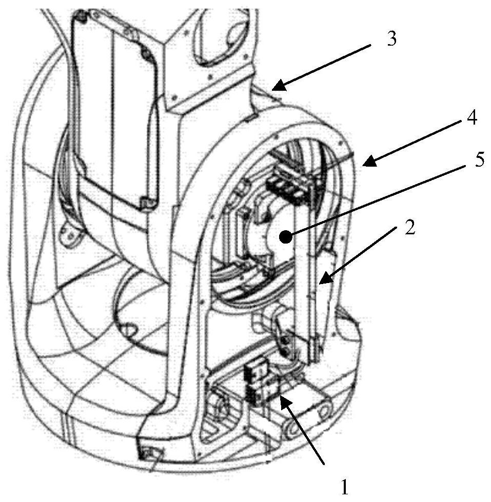
[0035] Please refer to figure 2 and image 3 , the present invention provides a multi-joint industrial robot using ordinary cables as power lines and control lines, including a base 10 arranged on the workbench (not shown in the figure), installed on the base 10 and winding perpendicular to the The swivel joint mount 20 that rotates on the axis of the workbench top, the first swivel joint 30 that is hinged to the swivel joint mount 20 and rotates around an axis parallel to the workbench top, is hinged on the first swivel joint 30 is away from one end of the swivel joint mounting seat 20 and rotates on an axis parallel to the first swivel joint 30. The second swivel joint 40 is installed on the second swivel joint 40 and rotates around the workbench surface. The connecting arm 50 , which is parallel to and rotates on an axis perpendicular to the rotation axis of the second rotating joint 40 , is installed on the side of the connecting arm 50 away from the second rotating join...


PUM


Abstract

The invention relates to a routing method for a robot rotating assembly. The routing method for the robot rotating assembly comprises the following steps of arranging a rotational joint mounting baseand a first rotational joint hinged to the rotational joint mounting base, so that the first rotational joint rotates around a shaft relative to the rotational joint mounting base; arranging a supporting piece located on the first rotational joint and coaxially rotating with the first rotational joint; arranging a clamping piece fixed on the rotational joint mounting base; and fixing one end of acable on the supporting piece, and enabling the other end of the cable to be fixed with the clamping piece. Compared with the prior art, the routing method for the robot rotational joint assembly provided by the invention has the advantage that cable abrasion between rotational joints can be reduced.

Description

technical field [0001] The invention relates to the technical field of robots, in particular to a wire routing method for a robot rotary joint assembly. Background technique [0002] As a symbol of the new generation of industrial revolution, robot technology gradually replaces manual processing and appears in the production of various products. In order to realize various complex actions performed by manual processing, in addition to bearing high loads, the robot joints also need to flexibly realize translation, rotation, swing and other actions. On the other hand, robots mainly rely on motors installed at each joint to achieve various actions. Various power lines, control lines and other cables are connected between the joints and move with the movement of the robot joints. In order to ensure that the cables can move with the joints, a certain length margin is reserved for the cables. However, if the length margin is too large, it will cause wear and tear on the cables a...

Claims


Application Information

Patent Timeline
Patent Type & Authority Applications(China)
IPC IPC(8): B25J17/02
CPCB25J17/02
Inventor 丁伟杨医华蔡国庆周文萧汉标
Owner 伯朗特机器人股份有限公司
Features
  • R&D
  • Intellectual Property
  • Life Sciences
  • Materials
  • Tech Scout
  • Unparalleled Data Quality
  • Higher Quality Content
  • 60% Fewer Hallucinations
Learn More