
Code scanning type numerical control sawing system and machining method thereof

A sawing and code scanning technology, which is applied in the direction of transmission system, sawing components, sawing equipment, etc., can solve the problem that it is difficult for the internal staff of the company to understand the real-time situation of the sheet in real time, the control parameters need manual input, and the degree of intelligence Low-level problems, to achieve the effect of facilitating daily processing, avoiding manual input, and high degree of intelligence

Active Publication Date: 2021-03-23
NANXING MACHINERY CO LTD
View PDF22 Cites 0 Cited by
  • Summary
  • Abstract
  • Description
  • Claims
  • Application Information

AI Technical Summary

Problems solved by technology

[0002] Existing CNC sliding table saws generally only realize numerical control on one set of positioning rests, and the other set of positioning rests still needs to be manually adjusted; moreover, although the positioning rests are numerically controlled, their control parameters still need to be adjusted. Manual input, low degree of intelligence, low positioning accuracy
Moreover, during the processing of the existing sliding table saw, it is difficult for the company's internal personnel to understand the real-time situation of sheet metal processing in real time.

Method used


Image

  • Code scanning type numerical control sawing system and machining method thereof
  • Code scanning type numerical control sawing system and machining method thereof
  • Code scanning type numerical control sawing system and machining method thereof

Examples


Embodiment Construction

[0071] The present invention will be further described below in conjunction with the accompanying drawings and specific embodiments.

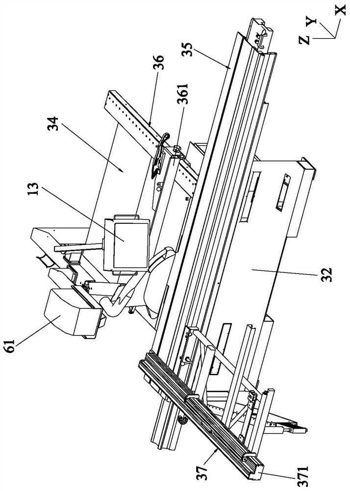
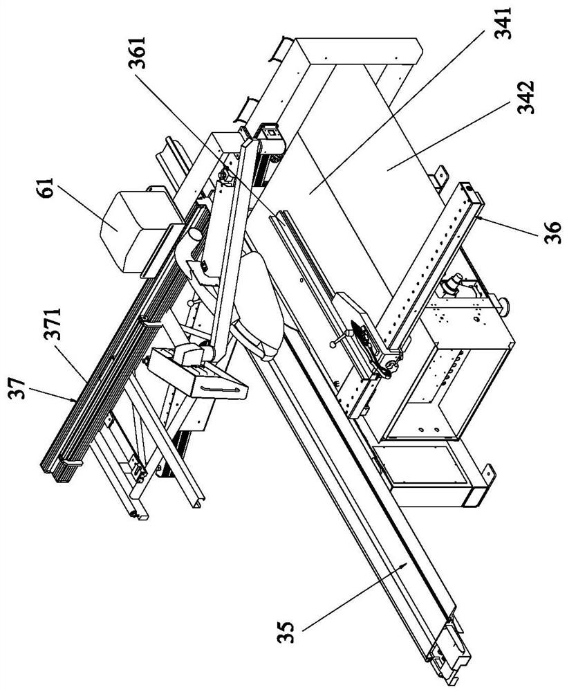
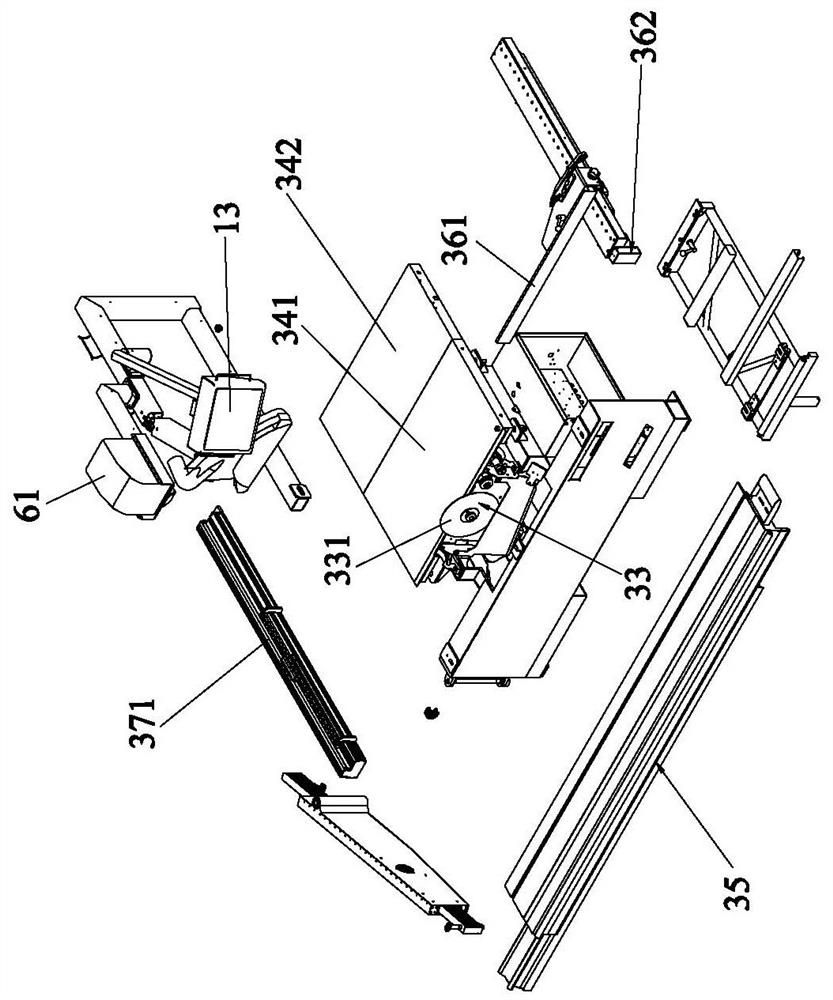
[0072] Such as Figure 1 to Figure 4 As shown, a code-scanning CNC sawing system includes an industrial computer 10 with a display screen 13, a PLC 20, a table saw, a first switch 41, a second switch 42, a database 43, a handheld unit 50, and a bar code and connected to the printer 61 of the industrial computer 10, the scanning gun 63 for scanning the two-dimensional code on the plate to be processed, and at least one PC 62;

[0073] The display screen 13 is a touch screen. The industrial computer 10 is communicated with the first switch 41 through Ethernet, and the first switch 41 is respectively connected to the PLC 20 and the second switch 42 through the Ethernet, and the second switch 42 is a LAN switch. Switch 42 connects PC 62 through Ethernet;

[0074] The sliding table saw includes a CNC controller 31, a frame 32 and a sawing device ...


PUM


Abstract

The invention relates to a code scanning type numerical control sawing system and a machining method thereof. The numerical control sawing system comprises an industrial personal computer, a PLC, a sliding table saw, a first switch, a second switch, a database, a scanning gun and a PC; the sliding table saw comprises a CNC controller, a longitudinal backup plate device and a transverse backup plate device; the CNC controller controls and is connected with a sawing device, a first driving mechanism of the longitudinal backup plate device and a second driving mechanism of the transverse backup plate device; and to-be-machined plate information associated with the two-dimensional code and positioning and machining programs of the to-be-machined plate information are stored in the database. After code scanning, two backup plates are controlled to move to achieve automatic positioning of the plates, the intelligent degree is high, manual input is avoided, the positioning machining precisionis high, the machining cost is reduced, and the machining efficiency is improved; wiring is simple, daily machining is facilitated, the workload of workers is reduced, and internal personnel of a company can know the real-time situation of plate machining conveniently; and in addition, the machining method is easy to operate, the automation degree and the positioning and machining precision are high, and the workload of operators is reduced.

Description

technical field [0001] The invention relates to the technical field of a numerical control sawing system, in particular to a code-scanning numerical control sawing system and a processing method thereof, which are mainly used in sliding table saws. Background technique [0002] Existing CNC sliding table saws generally only realize numerical control on one set of positioning rests, and the other set of positioning rests still needs to be manually adjusted; moreover, although the positioning rests are numerically controlled, their control parameters still need to be adjusted. Manual input, low degree of intelligence, low positioning accuracy. Moreover, during the processing of the existing sliding table saw, it is difficult for the company's internal personnel to understand the real-time situation of sheet metal processing in real time. [0003] Therefore, in the patent application of the present invention, the applicant has carefully studied a code-scanning CNC sawing syste...

Claims


Application Information

Patent Timeline
Patent Type & Authority Applications(China)
IPC IPC(8): B27G19/00H04L29/08G08B21/18
CPCB27G19/00H04L67/12G08B21/18
Inventor 石文昌陶宏健刘沅湘
Owner NANXING MACHINERY CO LTD
Learn More