Umbrella-shaped roller cam rotating table

A roller cam, rotary table technology, applied in belt/chain/gear, transmission, mechanical equipment, etc., can solve the problems of difficult cam tooth surface processing, stress concentration, excessive wrap angle, etc., and achieve good economic benefits and social benefits, meet the requirements of machining accuracy, and increase the effect of structural strength

Pending Publication Date: 2021-03-23
上海联紫能源科技有限公司
View PDF0 Cites 0 Cited by
  • Summary
  • Abstract
  • Description
  • Claims
  • Application Information

AI Technical Summary

Problems solved by technology

[0004] In view of the above-mentioned shortcomings of the prior art, the purpose of the present invention is to provide an umbrella-type roller cam rotary table, which is used to solve the lack of material, stress concentration, and insufficient strength of the tooth root of the worm shaft existing in the prior art; The tooth top of the worm is short of material, the wrap angle is too large, and it is difficult to process; the arrangement of the roller mounting holes interferes with each other; the cam tooth surface is difficult to process and cannot meet the processing accuracy requirements

Method used


Image

  • Umbrella-shaped roller cam rotating table
  • Umbrella-shaped roller cam rotating table
  • Umbrella-shaped roller cam rotating table

Examples


Embodiment 1

[0037] Embodiment 1. The vertical cylinder of the present invention is in front of the horizontal cylinder:

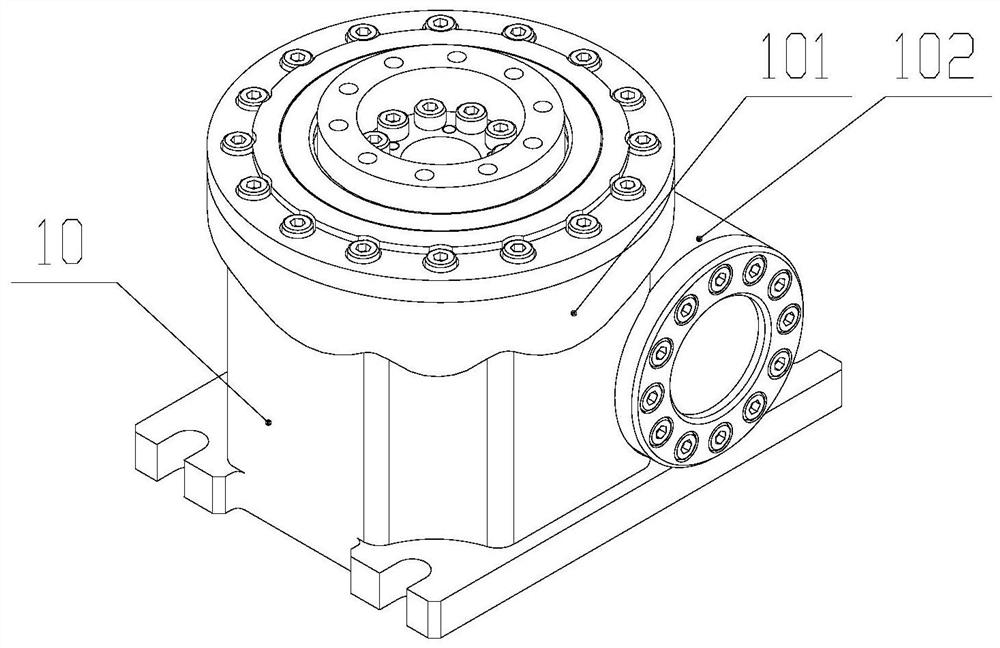
[0038] Such as figure 1 As shown, the present invention provides an umbrella-type roller cam rotary table, which is composed of a cabinet 10, a turret mechanism and a cam mechanism. The bottom plate of the ring is formed, the axis of the vertical cylinder 101 is perpendicular to the axis of the horizontal cylinder 102; the vertical cylinder 101 and the horizontal cylinder 102 interpenetrate;

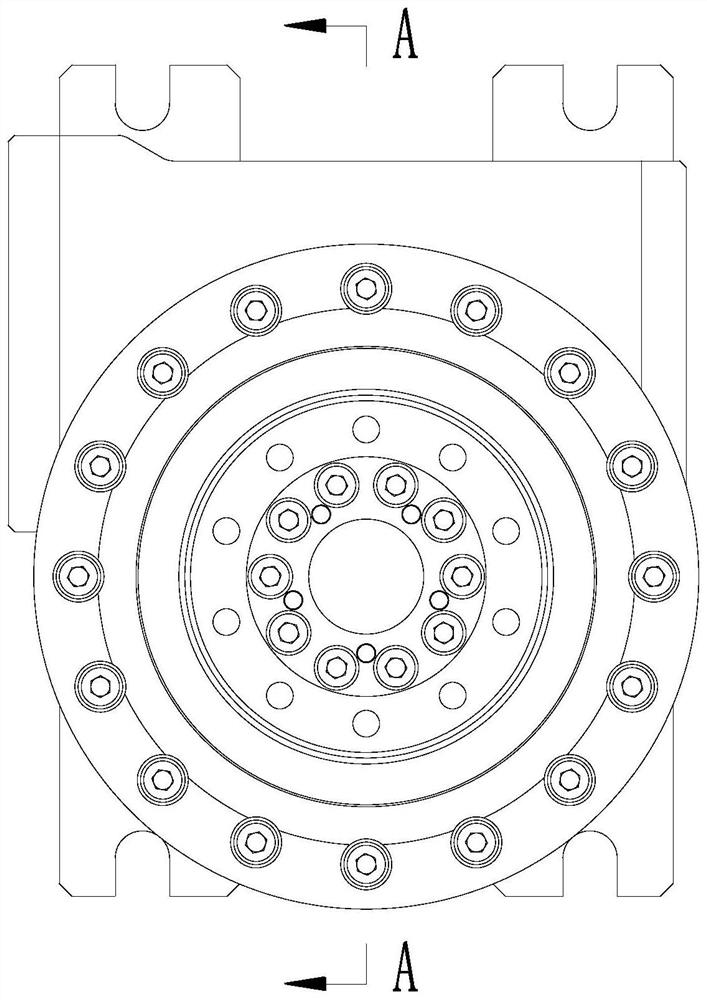
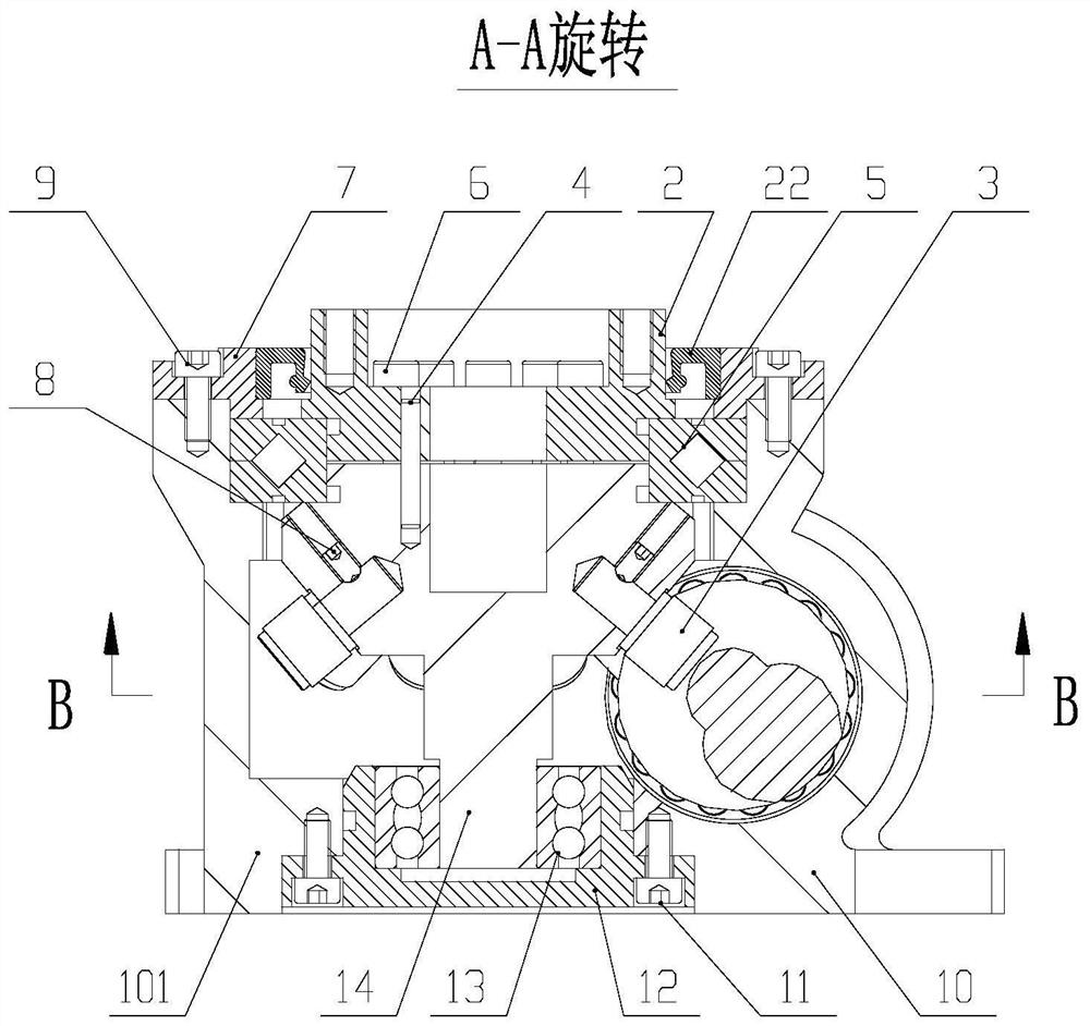
[0039] Such as figure 2 , image 3 As shown, a turret mechanism is arranged in the vertical cylinder body 101, and the turret mechanism is arranged along the axis of the vertical cylinder body 101. The turret mechanism is sequentially provided with a turntable 2, a turret 14, and a second seat plate 12 from top to bottom. Wherein the outer ring of the turntable 2 is provided with first seat plates 7 arranged at intervals; the turntable 2 is fixed on the top of the turret 14 b...

Embodiment 2

[0058] Embodiment 2, the vertical cylinder of the present invention is behind the horizontal cylinder:

[0059] Such as Figure 5 , Figure 6 As shown, a turret mechanism is arranged in the vertical cylinder body 101, and the turret mechanism is arranged along the axis of the vertical cylinder body 101. The turret mechanism is sequentially provided with a turntable 2, a turret 14, and a second seat plate 12 from top to bottom. Wherein the outer ring of the turntable 2 is provided with first seat plates 7 arranged at intervals; the turntable 2 is fixed on the top of the turret 14 by at least one cylindrical pin 4 and several first screws 6 evenly distributed around the circumference;

[0060] The turret 14 is provided with a circular platform with a large upper part and a smaller one. Several rollers 3 are distributed on the side of the circular platform of the turret 14 in an umbrella shape. Several rollers 3 are evenly distributed around the circumference along the side of t...


PUM


Abstract

The invention provides an umbrella-shaped roller cam rotating table. The umbrella-shaped roller cam rotating table is composed of a machine box, a turret mechanism and a cam mechanism. The machine boxis composed of a vertical cylinder, a transverse cylinder and a bottom plate on an outer ring of the bottom face of the vertical cylinder, wherein the axis of the vertical cylinder is perpendicular to the axis of the transverse cylinder. The vertical cylinder and the transverse cylinder are communicated with each other. The turret mechanism is arranged in the vertical cylinder, the turret mechanism is sequentially provided with a rotary disc, a turret and a second seat plate from top to bottom, and first seat plates are arranged on the outer ring of the rotary disc at intervals. A plurality of rollers evenly distributed around the circumference are arranged on an outer ring of the side face of a turret circular truncated cone, and any roller is fixed to the turret through a jackscrew perpendicular to the roller. A cam mechanism is arranged in the transverse cylinder and comprises a worm shaft, wherein at least two worm teeth with variable spiral angles are arranged on the worm shaft,and tooth grooves between every two worm teeth are in contact with the rollers. A first oil seal is arranged in a gap between the first seat plates and the rotary disc. The umbrella-shaped roller camrotating table is reasonable in structure, and the structural strength of the worm shaft is improved; and the machining difficulty of the cam tooth surface is reduced.

Description

technical field [0001] The invention belongs to the technical field of industrial equipment, and particularly relates to an umbrella-shaped roller cam rotary table, which is suitable for lifting transportation, engineering machinery, metallurgy, mining, petrochemical, construction machinery, light industry textiles, medical equipment, automobiles, ships, In industrial industries such as weapons and aerospace, it is mainly used in the mechanical arm of high-precision robots, the turntable of high-precision machine tools, the reducer and indexing plate of high-precision automatic production lines. Background technique [0002] In the cam rotation mechanism of the prior art, the cam adopts a toroidal worm with rectangular teeth (tooth angle is 0), and the outer ring of the turntable is provided with several evenly distributed rollers, and the teeth of the rollers and the rectangular teeth of the toroidal worm The grooves make contact, and the toroidal worm pushes on the rollers...

Claims


Application Information

Patent Timeline
Patent Type & Authority Applications(China)
IPC IPC(8): F16H37/12
CPCF16H37/12
Inventor 张德明
Owner 上海联紫能源科技有限公司
Why Eureka
Try Eureka