Grain orientation imaging picture acquisition auxiliary device and acquisition method

A technology of grain orientation and auxiliary devices, applied in instruments, microscopes, optics, etc., can solve problems such as poor universality, achieve low cost, and solve the effect of increasing production costs

Active Publication Date: 2021-03-23
CHINA HANGFA GUIZHOU LIYANG AVIATION POWER CO LTD
View PDF8 Cites 0 Cited by
  • Summary
  • Abstract
  • Description
  • Claims
  • Application Information

AI Technical Summary

Problems solved by technology

[0003] Optical digital microscopes are equipped in most laboratories. If electron backscatter diffraction technology is used, scanning electron microscope and electron backscatter diffraction probe equipment need to be purchased at the same time. The whole set of equipment is about 1 million; The cost is about 100,000. Different alloys need to develop different dyeing methods, and the universality is poor.

Method used


Image

  • Grain orientation imaging picture acquisition auxiliary device and acquisition method
  • Grain orientation imaging picture acquisition auxiliary device and acquisition method
  • Grain orientation imaging picture acquisition auxiliary device and acquisition method

Examples


Embodiment Construction

[0027] The technical solution of the present invention is further described below, but the scope of protection is not limited to the description.

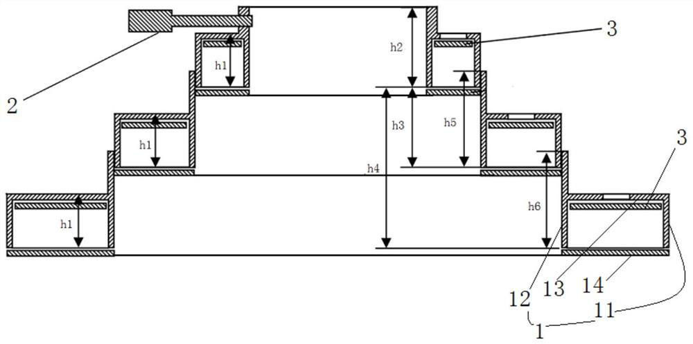
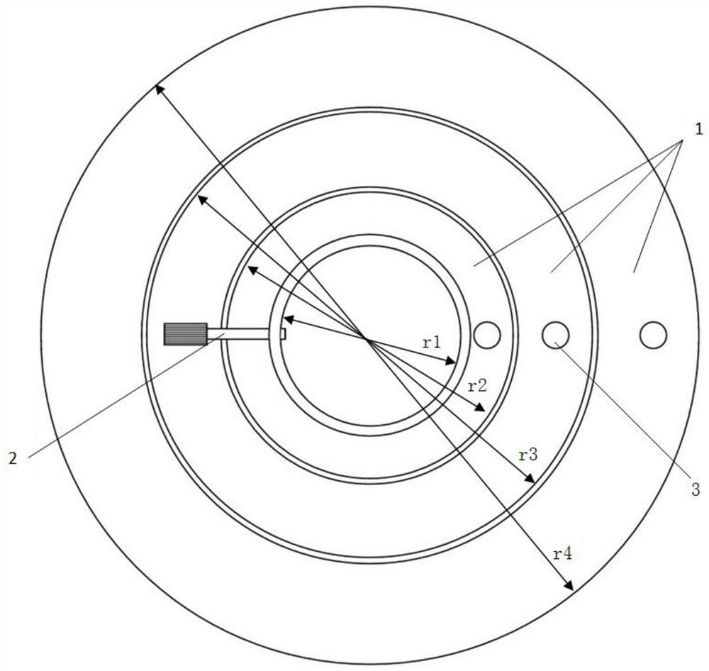
[0028] An auxiliary device for obtaining a grain orientation imaging map of the present invention, comprising: upper, middle and lower three-layer annular cavity 1 fixed sequentially in steps, the inner diameter of the three-layer annular cavity 1 decreases sequentially from bottom to top, The inner wall of the cavity 1 of the lower layer is fixedly connected with the outer wall of the cavity 1 of the middle layer, and the inner wall of the cavity 1 of the middle layer is fixedly connected with the outer wall of the cavity 1 of the upper layer;

[0029] The cavity 1 includes an outer side body 11, an inner side body 12, a top side body 13, and a bottom side body 14 which are sequentially fixed and closed to form the cavity; Ring surface light source;

[0030] The three-layer cavity 1 is equipped with an annular COB package LED lam...


PUM


Abstract

The invention discloses a grain orientation imaging picture acquisition auxiliary device and an acquisition method. The grain orientation imaging picture acquisition auxiliary device comprises an upper-layer annular cavity, a middle-layer annular cavity and a lower-layer annular cavity which are sequentially fixed in a stepped mode. The cavity comprises an outer side face body, an inner side facebody, a top face body and a bottom face body which are sequentially and fixedly sealed to form the cavity. The bottom face body is made of a white semitransparent transparent material; annular lamp bodies with different primary colors are installed in cavities of the three layers. Light rays of the lamp body are diffused through the bottom face body to form an annular surface light source, light rays of the annular surface light source irradiate the alloy grain surface on the object placing table, and then an optical digital microscope obtains a large-area grain orientation imaging picture. Because the brightness of the three layers of light sources with different colors reflected by the grains with different orientations is different, the colors of the grains with different orientations in the obtained image are different, and the colors of the grains with the same orientation are the same, a grain orientation imaging picture is obtained; the problems that the production cost is increased, the electron backscatter diffraction efficiency is low and the phase dyeing technology universality is poor due to the fact that the cost for purchasing electron backscatter diffraction equipment or phase dyeing technology research and development is increased are solved.

Description

technical field [0001] The invention relates to an acquisition auxiliary device and an acquisition method of a grain orientation imaging map, belonging to the technical field of alloy grain detection. Background technique [0002] At present, the main technologies for obtaining orientation imaging images include electron backscatter diffraction (EBSD) and phase staining technology. Electron backscatter diffraction technology detects the Kikuchi pattern at each point, and then draws the entire orientation imaging image. The sample preparation steps are complicated and time-consuming. Due to the limited area of ​​the acquired grain image and the long time, the efficiency of detecting alloy grains is low. The phase dyeing technique can only obtain the orientation imaging map of a small amount of phases, and it is still in the research stage, and its effective application is seldom. [0003] Optical digital microscopes are equipped in most laboratories. If electron backscatter ...

Claims


Application Information

Patent Timeline
Patent Type & Authority Applications(China)
IPC IPC(8): G02B21/08G02B21/00
CPCG02B21/084G02B21/0004
Inventor 杨玉川李永斌李巍熊勇汤浩
Owner CHINA HANGFA GUIZHOU LIYANG AVIATION POWER CO LTD
Why Eureka
Try Eureka