
High-precision lower drive type roller driving mechanism

A technology of roller mechanism and driving mechanism, which is applied in the direction of mechanical thickness measurement, instruments, manufacturing tools, etc., and can solve the problems of shaft workpieces that cannot meet the requirements of high-precision straightness

Active Publication Date: 2021-03-26
中机试验装备股份有限公司
View PDF20 Cites 0 Cited by
  • Summary
  • Abstract
  • Description
  • Claims
  • Application Information

AI Technical Summary

Problems solved by technology

[0004] For roller shafts, ball screws, and printing machine guide shafts, the straightness requirements are increasing day by day, and the straightness is required to be ≤0.02mm. Due to processing and assembly errors of the traditional roller lower drive device, the radial runout of the rollers is 0.01-0.05mm, and the workpiece rotation is repeated. The measurement error is roughly between 0.01mm-0.1mm, so the traditional driving device under the roller cannot meet the high-precision straightness requirements for shaft workpieces

Method used


Image

  • High-precision lower drive type roller driving mechanism
  • High-precision lower drive type roller driving mechanism
  • High-precision lower drive type roller driving mechanism

Examples


Embodiment Construction

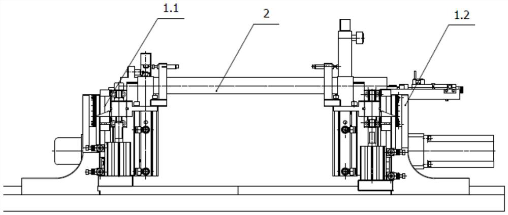
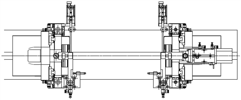
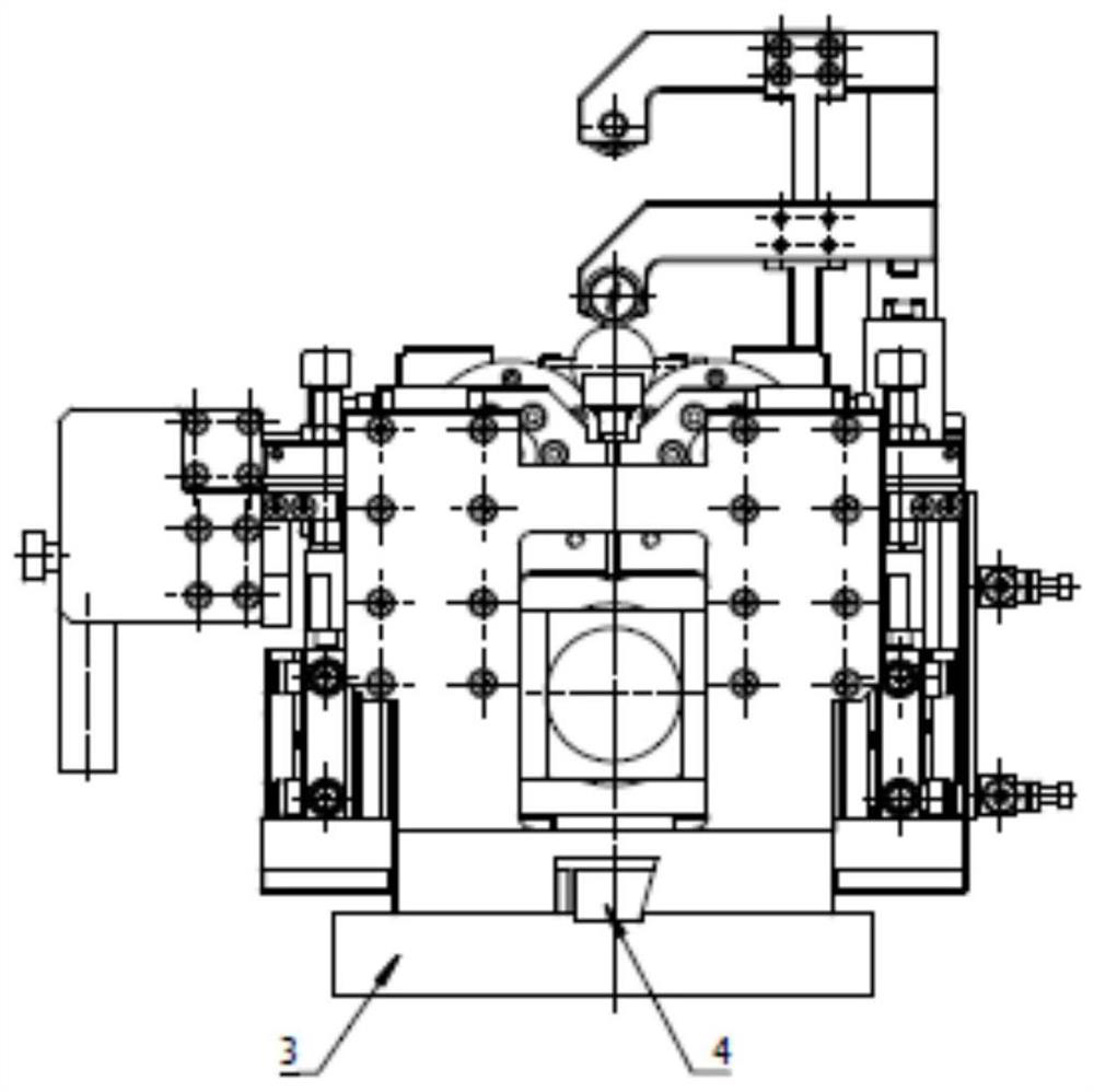
[0043] It includes two parts, the driven end 1.1 of the high-precision roller lower drive mechanism and the active end 1.2 of the high-precision roller lower drive mechanism. It cooperates with the upper surface of the workbench 3 and can slide on the surface of the workbench. The center of the upper surface of the workbench 3 is installed with a center guide rail 4. The cross section of the center guide rail 4 is in the shape of a single dovetail. The driven end of the high-precision roller drive mechanism is 1.1 And the fixed bracket 1.2.6-3 of the active end 1.2 of the high-precision roller lower drive mechanism has a single dovetail groove structure, which matches the dovetail slope of the center guide rail 4, and can adjust its installation position on the center guide rail 4, and can Lock the locking screw 1.2.6-2 on the inclined surface of the center guide rail 4, the driving end 1.2 of the high-precision roller lower driving mechanism and the driven end 1.1 of the high-...


PUM


Abstract

The invention relates to a high-precision lower drive type roller driving mechanism, and belongs to the field of shaft lever correction. The high-precision lower drive type roller driving mechanism comprises a high-precision roller lower drive mechanism driven end and a high-precision roller lower drive mechanism driving end, the lower surfaces of the high-precision roller lower drive mechanism driven end and the high-precision roller lower drive mechanism driving end are planes, and the planes are matched with the upper surface of a workbench and can slide on the surface of the workbench. Themechanism can achieve rotation driving of various shaft rod parts such as polished shafts and lead screws which are equal in diameter, variable in diameter, free of center holes, different in lengthand different in diameter. Compared with a conventional roller device, the high-precision lower drive type roller driving mechanism overcomes a series of technical defects of low precision, easy slipping, poor adaptability and the like when rotating measurement is carried out by taking a roller as a reference. The mechanism has the advantages of being high in rotation reference precision, wide inapplication range of workpieces, flexible and convenient to operate, convenient to adjust, capable of breaking through automatic shaft straightening with the outer circle as the reference and meetingthe high-precision straightness requirement, easy to assemble, compact in structure, convenient to produce and the like.

Description

technical field [0001] The invention belongs to the field of shaft rod correction, and is mainly used for automatic straightening equipment and detection equipment of shaft parts, and is widely used in screw rods in the petroleum industry, piston rods and cylinder barrels of hydraulic engineering cylinders, roller shafts of textile machinery equipment, and printing machinery. The straightening drive of the guide shaft and guide roller, the ball screw and other shaft parts required by various equipment. Background technique [0002] For a workpiece without a center hole, it is necessary to provide a supporting reference and driving power for its alignment or measurement. For the straightening machine, the driving device of the straightening machine is a device that drives the rotation measurement of the workpiece during the straightening process, and it is also the mechanical reference for the rotation measurement of the workpiece. The driving device drives the workpiece to ...

Claims


Application Information

Patent Timeline
IPC IPC(8): B21D3/02B21C51/00G01B5/06G01B21/00G01B11/26
CPCB21D3/02B21C51/00G01B5/06G01B21/00G01B11/26
Inventor 庄树明于明陈景光刘立陈城车立志牛加飞于洪星王大雷
Owner 中机试验装备股份有限公司
Learn More