Rapid steel plate cutting equipment for high-end equipment manufacturing

A rapid cutting and equipment technology, applied in welding equipment, manufacturing tools, laser welding equipment, etc., can solve the problems of wasting manpower, difficulty in collecting, and uncertain moving distance of steel plates, and achieve the effects of avoiding damage, facilitating collection, and saving manpower

Active Publication Date: 2021-03-26
广东铨琪机械装备有限公司
View PDF15 Cites 2 Cited by
  • Summary
  • Abstract
  • Description
  • Claims
  • Application Information

AI Technical Summary

Problems solved by technology

[0005] In order to overcome the disadvantages of manually pushing materials in the prior art, which wastes manpower, the steel plates after cutting are scattered randomly, it is difficult to collect, and the moving distance of steel plates is not fixed. The technical problem to be solved is to provide an automatic fast cutting, automatic transmission of steel plates, and automatic catch High-end equipment manufacturing high-end steel plate cutting equipment that assists in dropping steel plates, automatically arranges steel plates, and restricts the movement of steel plates

Method used


Image

  • Rapid steel plate cutting equipment for high-end equipment manufacturing
  • Rapid steel plate cutting equipment for high-end equipment manufacturing
  • Rapid steel plate cutting equipment for high-end equipment manufacturing

Examples


Embodiment 1

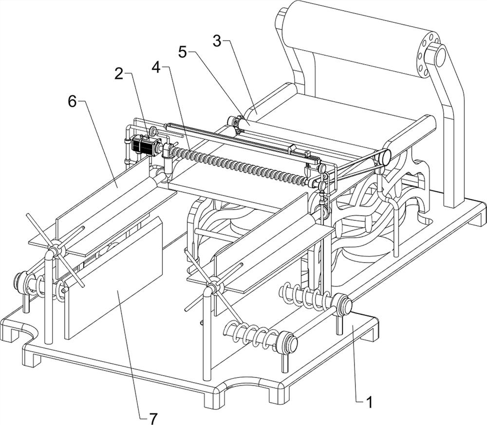
[0030] A high-end equipment manufacturing steel plate rapid cutting equipment, such as figure 1 , figure 2 and image 3 As shown, it includes a base 1, a motor 2, a placement assembly 3 and a cutting assembly 4. The upper right side of the base 1 is provided with a placement assembly 3, the middle part of the upper side of the base 1 is provided with a cutting assembly 4, and the upper part of the cutting assembly 4 is provided with a motor 2.

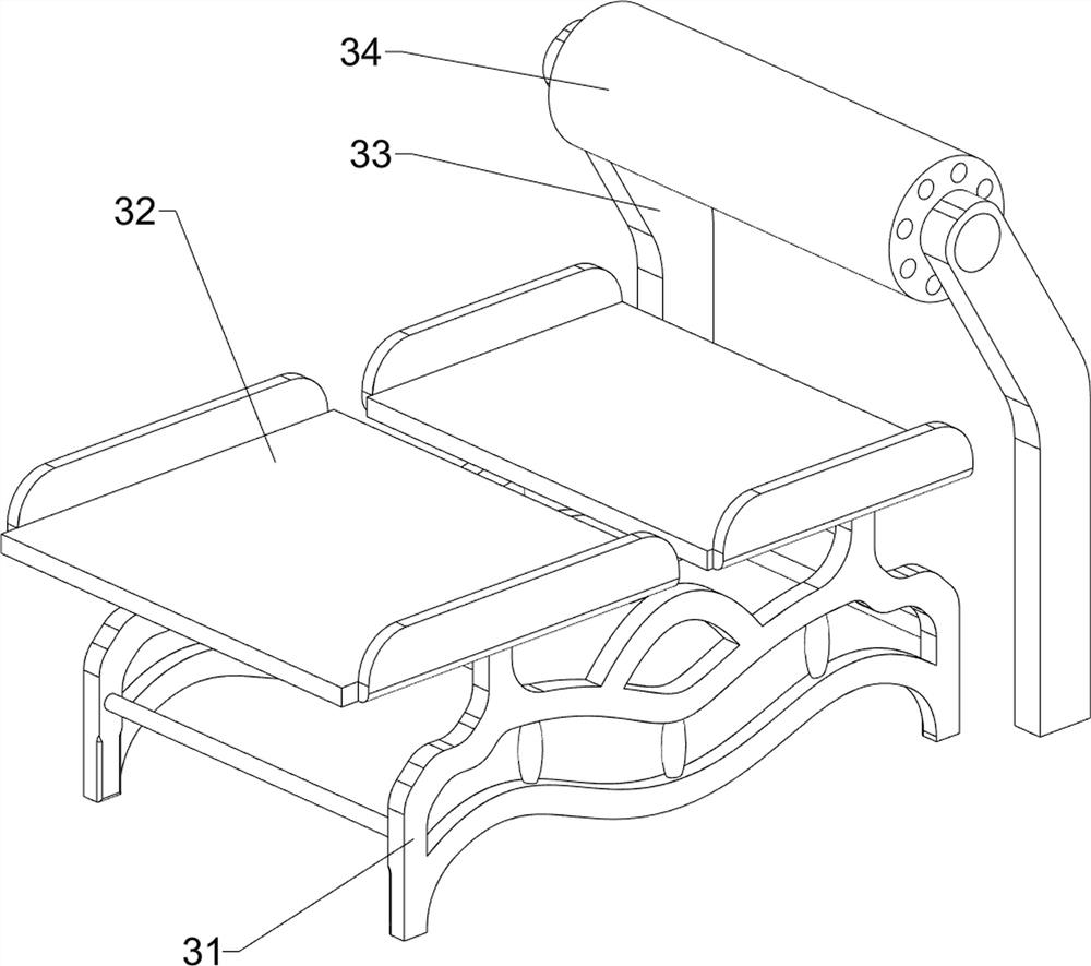
[0031] The placement assembly 3 includes a first support frame 31, a placement plate 32, a first support rod 33, and a first roller 34. The upper right side of the base 1 is connected with the first support frame 31, and the left and right sides of the upper part of the first support frame 31 are connected. There is a placement plate 32 , the upper right side of the base 1 is symmetrically connected with a first support rod 33 front and back, and a first roller 34 is connected in a rotational manner between the upper parts of the fir...

Embodiment 2

[0035] On the basis of Example 1, such as Figure 4 , Figure 5 , Figure 6 , Figure 7 and Figure 8 As shown, a push assembly 5 is also included. The push assembly 5 includes a third support rod 51, a second roller 52, a transmission assembly 53 and a gear assembly 54. The upper right side of the base 1 is connected with a third support rod 51 symmetrically front and rear. The upper part of the three support rods 51 is connected with the second roller 52 symmetrically rotating up and down, the second roller 52 is located between the placement plates 32, and the transmission assembly is connected between the front side of the transmission shaft of the upper second roller 52 and the front side of the worm 43 53 , a gear assembly 54 is connected between the rear sides of the transmission shaft of the second drum 52 .

[0036] When the worm 43 reversely rotates, it will drive the transmission assembly 53 to rotate, thereby driving the upper second roller 52 and the gear asse...


PUM


Abstract

The invention relates to cutting equipment, and especially relates to rapid steel plate cutting equipment for high-end equipment manufacturing. The technical problem to be solved is to provide rapid steel plate cutting equipment for high-end equipment manufacturing, which can automatically and rapidly cut, automatically convey a steel plate, automatically receive the steel plate, assist in falling, automatically tidy the steel plate and limit the movement of the steel plate. The rapid steel plate cutting equipment for high-end equipment manufacturing comprises a base, a cutting assembly and amotor, wherein a placing assembly is arranged at one side of the upper part of the base; the cutting assembly is arranged at the middle part of the upper side of the base; and the motor is arranged onthe upper part of the cutting assembly. According to the invention, the steel plate is rolled on a first roller and pulled to move leftwards, a first connecting rod presses a first button, a motor isstarted forwards and a laser spray head is started to drive a worm to rotate, so that the laser spray head is driven to move forwards to cut the steel plate, the effect of automatically and repeatedly cutting the steel plate is achieved, and rapidness and convenience are achieved.

Description

technical field [0001] The invention relates to a cutting device, in particular to a rapid cutting device for steel plates for high-end equipment manufacturing. Background technique [0002] Steel plate is a flat steel material that is poured with molten steel and pressed after cooling. In construction and manufacturing, steel plate is widely used because of its high temperature, high pressure, low temperature, corrosion resistance, and wear resistance. [0003] Steel plates are used in the production and manufacture of some high-end equipment. In order to make the steel plates better put into processing and manufacturing, it is necessary to cut the steel plates. The traditional steel plate cutting mainly relies on the user to intermittently pull the steel plates to move to the appropriate position. Drive the laser nozzle to move to cut the steel plate. This method first moves the steel plate manually, which consumes manpower and is inefficient. Secondly, the cut steel plate...

Claims


Application Information

Patent Timeline
Patent Type & Authority Applications(China)
IPC IPC(8): B23K26/38B23K26/70
CPCB23K26/38B23K26/702Y02P70/10
Inventor 张梨
Owner 广东铨琪机械装备有限公司
Why Eureka
Try Eureka