

Large-span welded ball net rack ground assembly integral lifting construction method
It is a technology of overall lifting and ground assembly, which is applied in the direction of architecture and building structure, etc., to achieve the effect of improving installation quality, saving labor and material costs, and ensuring safe construction
Pending Publication Date: 2021-03-26
CHINA MCC 2 GRP CO LTD
View PDF4 Cites 6 Cited by
- Summary
- Abstract
- Description
- Claims
- Application Information
AI Technical Summary
Problems solved by technology
[0004] For this reason, the present invention provides a large-span welded ball grid grou
Method used
View moreImage
Smart ImageViewing Examples

Examples
 PUM
| Property | Measurement | Unit |
|---|---|---|
| Surface roughness | aaaaa | aaaaa |
Abstract
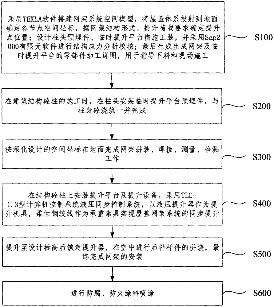
The invention discloses a large-span welded ball net rack ground assembly integral lifting construction method. The large-span welded ball net rack ground assembly integral lifting construction methodcomprises the steps that a roof system is projected to the ground to determine the space coordinates of all joints, and the position of a lifting point is determined according to the net rack structure form and the lifting load requirement; column head embedded parts are designed, and a platform measure tool is temporarily lifted; finally, a part machining detail drawing for generating a net rackand a temporary lifting platform is generated and used for guiding discharging and field construction; during construction of building a structural concrete column, a temporary lifting platform embedded part is installed on a column head, and pouring of the temporary lifting platform embedded part and column body concrete is completed together; net rack assembling, welding, measuring and detecting work is completed on the ground according to the space coordinates of the deepening design; a lifting platform and lifting equipment are installed on the structural concrete column, a hydraulic lifter serves as a lifting machine tool, and a flexible steel strand serves as a bearing rigging to achieve synchronous lifting of the roof net rack system; a lifter is locked after being lifted to the designed elevation, the rear supplementary rod pieces are assembled in the air, and finally installation of the net rack is completed; and an anti-corrosion and fireproof coating is sprayed.
Description
technical field [0001] The invention relates to the technical field of building construction, in particular to an overall lifting method for ground assembly of a large-span welded ball net frame. Background technique [0002] The large-span welded spherical grid structure is widely used in the roof load bearing of airports, gymnasiums, exhibition centers, etc. in recent years due to its novel and beautiful appearance, strong regularity of rods, good integrity, large space rigidity, and good seismic performance. structure; it is a new type of roof load-bearing structure, which belongs to the multi-time hyperstatic space structure system, which changes the stress state of the flat roof truss structure and can bear loads from all sides; due to various grid structure shapes, The installation methods are different for different spans; the traditional grid installation methods include the high-altitude bulk method of erecting a full house scaffolding, the overall hoisting method, ...
Claims
Login to View More Application Information
Patent Timeline
 IPC IPC(8): E04B1/35
CPCE04B1/3511E04B2001/3577
Inventor张宝平陈克温旭
OwnerCHINA MCC 2 GRP CO LTD