Digital remote transmission type monitor with single trigger module

A monitor and remote transmission technology, applied in the field of arrester monitoring use system and device structure design, can solve the problems of inconsistency of the monitoring data of the arrester monitoring device, inconsistency of the monitoring data of the counter and the milliamp meter, inaccurate monitoring of the use condition of the arrester, etc. Achieve the effect of avoiding the possibility of fault and false alarm, increasing labor intensity and timely maintenance

Pending Publication Date: 2021-03-26
平高东芝(廊坊)避雷器有限公司 +1
View PDF0 Cites 0 Cited by
  • Summary
  • Abstract
  • Description
  • Claims
  • Application Information

AI Technical Summary

Problems solved by technology

[0006] During long-term use, due to the parallel connection of the counter circuit and the current measurement circuit, the counter and the milliampmeter measure their respective circuits separately, that is, separate monitoring data, and the monitoring data of the counter and milliammeter are prone to inconsistency
For the arrester monitoring process, the counter circuit and the current measurement circuit are connected in parallel for measurement, which is equivalent to: the measurement of the number of lightning strikes and the leakage current is measured by two separate modules, which is easy to cause inconsistency in the data monitored by the two circuits, resulting in failure False alarms, increase the labor intensity of workers, and seriously increase maintenance and overhaul costs
[0007] It can be seen that in the prior art, the arrester monitoring device has the problems of inconsistency of monitoring data, prone to false alarms of faults, and inaccurate monitoring of the use status of the arrester.

Method used


Image

  • Digital remote transmission type monitor with single trigger module
  • Digital remote transmission type monitor with single trigger module
  • Digital remote transmission type monitor with single trigger module

Examples


Embodiment Construction

[0044] The digital remote transmission monitor of the one-shot module of the present invention will be further described in detail below in conjunction with the accompanying drawings and the embodiments of the present invention.

[0045] It should be noted that, in the case of no conflict, the embodiments in the present application and the features in the embodiments can be combined with each other. The present invention will be described in detail below with reference to the accompanying drawings and examples.

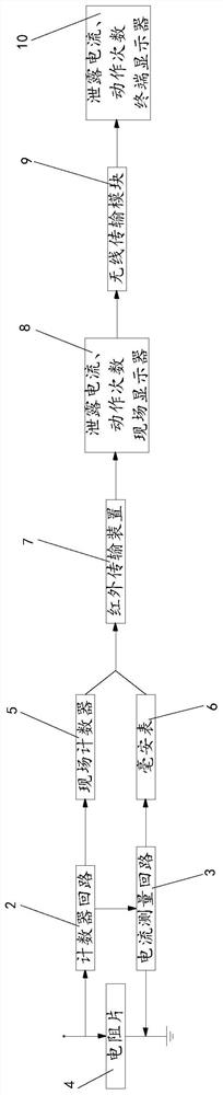
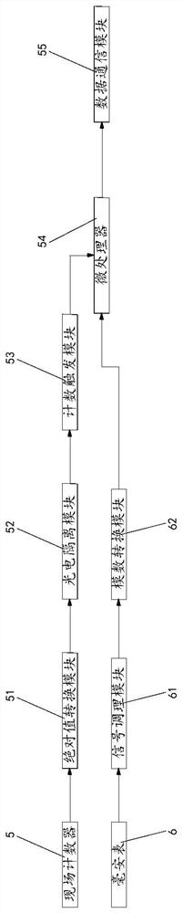
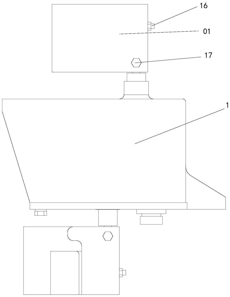
[0046] Such as Figure 1 to Figure 8 As shown, the digital remote monitor of the one-shot module includes: a counter loop 2 and a current measurement loop 3 inside the monitor body 1, the counter loop 2 and the current measurement loop 3 are connected in series, the counter loop 2, the current measurement loop The series circuit of the loop 3 is connected in parallel with the resistor sheet 4; the monitoring device for the arrester is realized as a single-trigger cir...


PUM


Abstract

The invention discloses a digital remote transmission type monitor with a single trigger module, and the monitor comprises a counter loop and a current measurement loop which are arranged in a monitorbody; the counter loop is connected with the current measurement loop in series, and a series circuit of the counter loop and the current measurement loop is connected with a resistor disc in parallel. The counter loop is connected with an on-site counter, and the current measurement loop is connected with a milliammeter. The problems that in the prior art, in the lightning arrester monitoring process, a counter loop and a current measurement loop are connected in parallel for measurement, equivalently, the number of lightning strokes and the leakage current are measured through two independent modules, in this way, monitoring data of the two loops are inconsistent easily, and fault false alarm is caused are solved. According to the digital remote transmission type monitor with the singletrigger module, the monitoring device for the lightning arrester is a single trigger loop, so that the single trigger module is realized, the consistency of monitoring data is ensured, and the monitoring accuracy of the lightning arrester is ensured.

Description

technical field [0001] The invention relates to the technical field of lightning arrester monitoring system and device structure design, in particular to a digital remote transmission monitor with a single-trigger module. Background technique [0002] In the high-voltage power grid, the arrester is an important device to protect power equipment from overvoltage damage, and its reliable operation directly affects the safety of the high-voltage power grid. [0003] Zinc oxide varistors have good nonlinear volt-ampere characteristics. When the system voltage is lower than its varistor voltage, it is in a high-resistance state, and only a small (μA level) current mainly capacitive current passes through; when the voltage exceeds the varistor voltage of the zinc oxide resistor, it will be turned on immediately The zinc oxide resistor makes it in a low-resistance state, absorbs the energy generated by the overvoltage, and limits the amplitude of the overvoltage. Because of its go...

Claims


Application Information

Patent Timeline
Patent Type & Authority Applications(China)
IPC IPC(8): G01R31/52G01R19/17G01R19/00G08C17/02G08C23/04
CPCG01R19/0092G01R19/17G08C17/02G08C23/04G01R31/52
Inventor 白立杰郎小华田宏伟张彦杰王草袁素梅李明刚刘凯李石磊李宝兵
Owner 平高东芝(廊坊)避雷器有限公司
Why Eureka
Try Eureka