
Three-dimensional imaging method based on reconfigurable electromagnetic surface array

An electromagnetic surface and three-dimensional imaging technology, applied in the field of security inspection, can solve the problem that millimeter-wave imaging technology is difficult to meet the needs of fast-passing human body security inspection in densely populated areas at the same time

Active Publication Date: 2021-03-26
BEIJING INSTITUTE OF TECHNOLOGYGY
View PDF7 Cites 0 Cited by
  • Summary
  • Abstract
  • Description
  • Claims
  • Application Information

AI Technical Summary

Problems solved by technology

[0009] However, the existing millimeter-wave imaging technology mentioned above is difficult to meet the needs of fast-passing human body security inspection in densely populated areas in terms of processing algorithms and system costs.

Method used


Image

  • Three-dimensional imaging method based on reconfigurable electromagnetic surface array
  • Three-dimensional imaging method based on reconfigurable electromagnetic surface array
  • Three-dimensional imaging method based on reconfigurable electromagnetic surface array

Examples


Embodiment Construction

[0043] Various exemplary embodiments, features, and aspects of the present disclosure will be described in detail below with reference to the accompanying drawings. The same reference numbers in the figures indicate functionally identical or similar elements. While various aspects of the embodiments are shown in the drawings, the drawings are not necessarily drawn to scale unless specifically indicated.

[0044] The word "exemplary" is used exclusively herein to mean "serving as an example, embodiment, or illustration." Any embodiment described herein as "exemplary" is not necessarily to be construed as superior or better than other embodiments.

[0045] In addition, in order to better illustrate the present disclosure, numerous specific details are given in the specific embodiments below. It will be understood by those skilled in the art that the present disclosure may be practiced without some of the specific details. In some instances, methods, means, components and circ...


PUM


Abstract

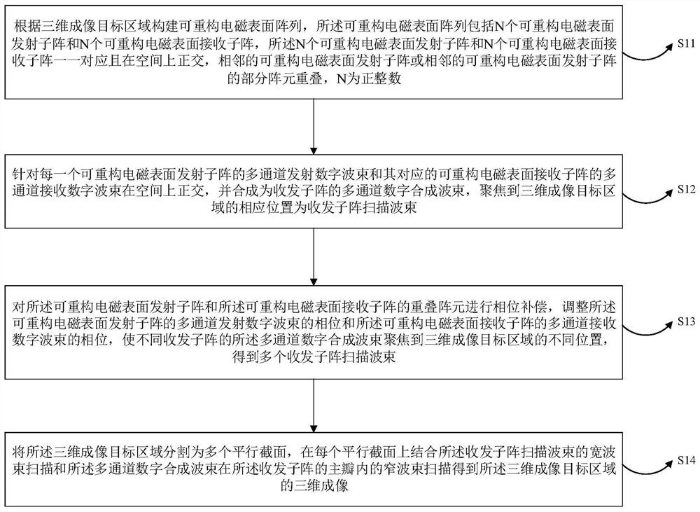
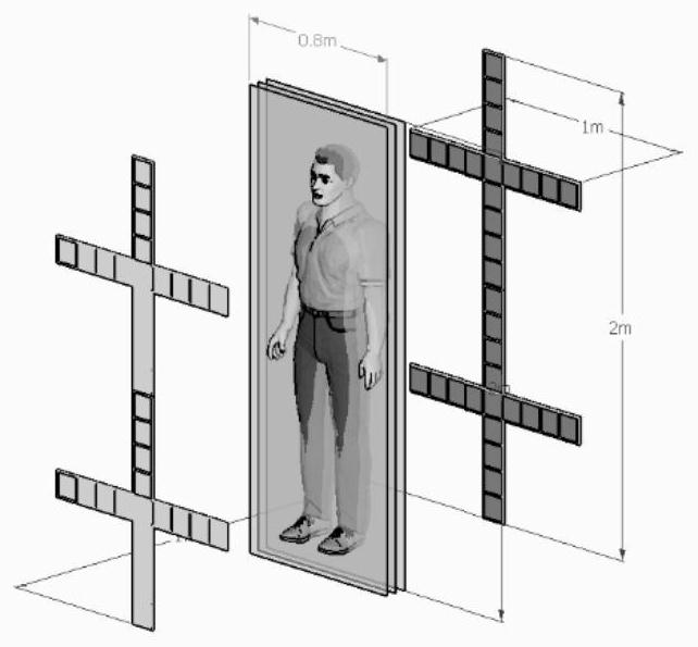
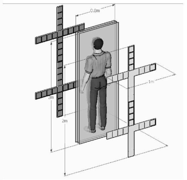
The disclosure provides a three-dimensional imaging method of the reconfigurable electromagnetic surface array, wherein a reconfigurable electromagnetic surface array is constructed according to a target area, N transmitting sub-arrays and the N receiving sub-arrays are corresponding and orthogonal, the array elements of the adjacent sub-arrays are partially overlapped, and N is a positive integer; the multichannel transmitting digital wave beams and the multichannel receiving digital wave beams corresponding to the multichannel transmitting digital wave beams are orthogonal to form multichannel digital synthesis wave beams of the transmitting-receiving subarrays, and the multichannel digital synthesis wave beams are focused to the corresponding positions of the target area to form transmitting-receiving subarray scanning wave beams; the phase compensation is performed on overlapped array elements of the transmitting sub-array and the receiving sub-array, so that the multi-channel digital synthesis wave beams can be focused to different positions of a target area; the target area is divided into a plurality of parallel sections, and three-dimensional imaging of the target area is obtained on each parallel section in combination with transmitting and receiving sub-array scanning beams and multi-channel digital synthesis beam scanning. By means of the technical scheme, the numberof spatial scanning times can be reduced by several orders of magnitude, the advantages of sparse array and real beam imaging are integrated, the pass-type rapid security check can be realized when the pedestrian volume is large, and the human body is rapidly scanned and imaged.

Description

technical field [0001] The invention belongs to the technical field of security inspection, and in particular relates to a three-dimensional imaging method based on a reconfigurable electromagnetic surface array. Background technique [0002] The issue of public safety is the focus of extensive attention of the international community. Airports, subways, stations, squares and other densely populated places are the main places where attacks occur, so higher requirements are placed on the accuracy, real-time performance, intelligence and environmental applicability of the security inspection system. [0003] In recent years, millimeter-wave security inspection imaging technology is a new type of security inspection technology. It has the advantages of high security, good penetration, and differences in electromagnetic scattering characteristics of different materials. It has become the mainstream development direction of human body security inspection technology. [0004] Mil...

Claims


Application Information

Patent Timeline
Patent Type & Authority Applications(China)
IPC IPC(8): G01S13/89G01S13/88G01V8/00G01V8/20
CPCG01S13/89G01S13/887G01V8/005G01V8/20
Inventor 李世勇赵国强王硕光敬汉丹孙厚军
Owner BEIJING INSTITUTE OF TECHNOLOGYGY
Learn More