In-band ultra-low envelope delay fluctuation filter

A filter, ultra-low group technology, applied in the field of filters, can solve the problems of complex structure, extremely low group delay fluctuation, inability to guarantee basic performance, etc., to achieve low cost, high out-of-band suppression, easy processing and effect achieved

Active Publication Date: 2021-03-26
UNIV OF ELECTRONICS SCI & TECH OF CHINA
View PDF10 Cites 0 Cited by
  • Summary
  • Abstract
  • Description
  • Claims
  • Application Information

AI Technical Summary

Problems solved by technology

[0004] The object of the present invention is to: provide a kind of in-band ultra-low group delay ripple filter, solve the complex structure of the current ultra-low group delay ripple filter , the problem of not being able to maintain extremely low group delay fluctuations while ensuring basic performance

Method used


Image

  • In-band ultra-low envelope delay fluctuation filter
  • In-band ultra-low envelope delay fluctuation filter
  • In-band ultra-low envelope delay fluctuation filter

Examples


Embodiment 1

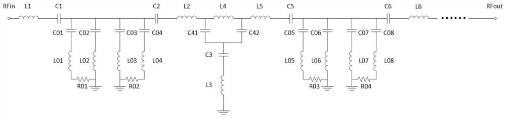
[0033] An in-band ultra-low group delay ripple filter provided by a preferred embodiment of the present invention, such as Figures 2 to 6 As shown, this embodiment introduces a third-order in-band ultra-low group delay filter, and the center frequency of the filter is 720 MHz.

[0034] This embodiment includes six resonant matching circuits (I-VI), three self-balanced resonant circuits (I-III) and two group delay compensation circuits (I, II).

[0035] The basic composition of the resonant matching circuit includes a first inductance L1 and a first capacitor C1, and the first inductance is connected in series with the first capacitor;

[0036] The basic composition of the self-balanced resonant circuit I includes a self-balanced resonant unit I and a self-balanced resonant unit II. The self-balancing resonant unit I includes a second inductor L01, a third inductor L02, a second capacitor C01, a third capacitor C02, and a first resistor R01. The second capacitor C01, the sec...


PUM


Abstract

The invention discloses an in-band ultra-low envelope delay fluctuation filter which comprises a resonance matching circuit, a self-balancing resonance circuit and a envelope delay compensation circuit. The resonance matching circuit comprises a first inductor and a first capacitor which are connected in series. The self-balancing resonance circuit comprises a self-balancing resonance unit I and aself-balancing resonance unit II. The self-balancing resonance unit I comprises a second inductor, a third inductor, a second capacitor, a third capacitor and a first resistor. The second capacitor,the second inductor and the first resistor are sequentially connected in series and the other end of the first resistor is grounded. The third capacitor and the third inductor are sequentially connected in series and the other end of the third inductor is grounded. The other end of the second capacitor is connected with the other end of the third capacitor. The self-balancing resonance unit II comprises a fourth inductor, a fifth inductor, a fourth capacitor, a fifth capacitor and a second resistor. The fourth inductor, the fourth capacitor and the second resistor are sequentially connected inseries and the other end of the second resistor is grounded. The fifth inductor and the fifth capacitor are sequentially connected in series and the other end of the fifth inductor is grounded.

Description

technical field [0001] The invention relates to the technical field of filters, in particular to the design of an in-band ultra-low group delay ripple filter. Background technique [0002] With the rapid development of wireless communication technology, higher and higher requirements are placed on the communication rate. With the improvement of wireless transmission rate, problems such as signal distortion and intersymbol interference have gradually become prominent, and communication quality is facing severe challenges. In a communication system, the signal information is included in the envelope. In order to achieve distortion-free signal transmission, it is necessary to ensure that the system group delay is constant within the working frequency band, otherwise it will cause distortion of signal transmission. The group delay fluctuation is mainly related to amplifiers, mixers, filters, etc., among which the in-band group delay fluctuation of the filter is the most critica...

Claims


Application Information

Patent Timeline
Patent Type & Authority Applications(China)
IPC IPC(8): H03H17/02
CPCH03H17/0219H03H17/0283
Inventor 石玉刘军尉旭波钟慧雷紫阳廉翅罗鸿飞
Owner UNIV OF ELECTRONICS SCI & TECH OF CHINA
Why Eureka
Try Eureka